Page 5?*,)(.82<&80;)@+.'(&*<'A)3;.0'.)80;;)BCDDDCD!!C$EFE5Item 64355
GH?:IJKLGIHMMHIKNLOHPIG)MKGI
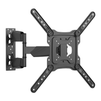
4. Once Wall Anchors are securely set into concrete,
use four Lag Bolts and Lag Bolt Washers to
install Wall Bracket to wall. Center Bracket
across mounting locations with mounting holes
flush against the wall. Refer to Figure C.
M07)U*;()
]B"^
M07)U*;()
R0'2.,)]B$^
R0;;)
H<82*,)
]B!^
R0;;)U,08_.()
]B^
?&7+,.)Q)
K<'(0;;&<7)G+33*,()H,9')(*)?;0()O0<.;)I%
P.0=)I%)*-<.,`')90<+0;)/.6*,.)0((082&<7)
(2&')3,*=+8(5))G*9.)I%`')-&;;)/.)=0907.=)*,)
80+'.)0),&'_)*6).;.8(,&8)'2*8_)&6)'8,.-')0,.)
(2,.0=.=)&<)(**)=..3;W5))Z0,/*,)?,.&72()I**;')&')
<*(),.'3*<'&/;.)6*,)=0907.)80+'.=)/W)60&;+,.)
(*)6*;;*-)I%)9*+<(&<7)&<'(,+8(&*<'A)&93,*3.,)
&<'(0;;0(&*<A)*,)&93,*3.,4;**'.)20,=-0,.5
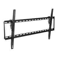
1. Unplug TV before threading any
Screw into the TV’s back panel.
2. Do not lay flat panel TV face down to install
Support Arms. Cover TV screen with a
towel or other soft material and tilt it against
the wall or another solid surface.
3. Locate the mounting holes on back of TV
and select mounting Screws (3, 4, 5 or 6)
that fit properly. If the TV included mounting
screws, use those screws instead.
4. Thread the Screws through the matching
Lock Washers (7, 8, 9 or 10), matching
Washers (11 or 12), the Support Arms (2a, 2b),
and into the mounting holes in the back of TV
panel. Use the Spacers (13) positioned as
shown if the bolts are too long or if the back
of the TV is not flat. Refer to Figure D.
L*(.1 If none of the Screws supplied are
an appropriate size, refer to TV owner’s
manual or contact TV manufacturer.
5. Torque Screws to the specification listed in
the TV owner’s manual to prevent loosening.
Do not overtighten to avoid TV damage.
G+33*,()
H,9')
]a0A)a/^
G8,.-')]#C!^
M*8_)R0'2.,)
]ECBb^
R0'2.,)]BBCBa^
G308.,)
]B#^
I%)U08_
?&7+,.)V
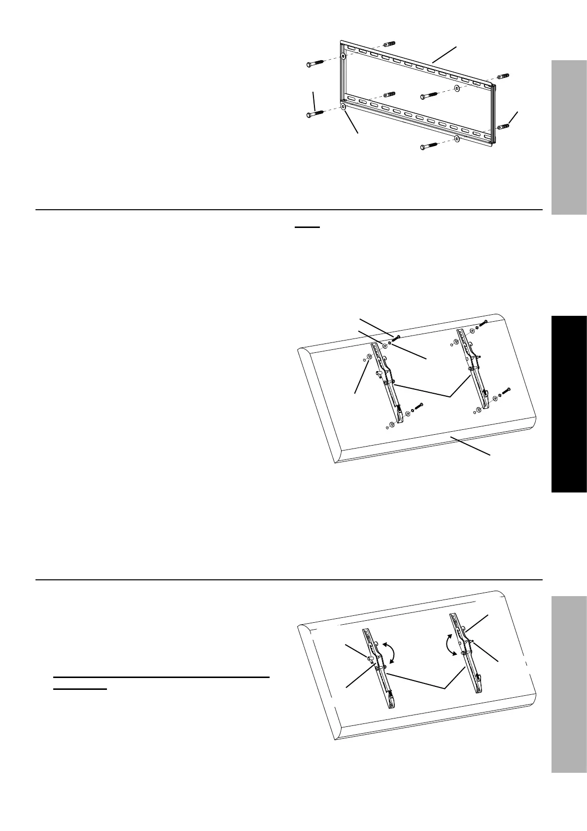
H=X+'(&<7)?;0()O0<.;)I%)H<7;.)U.6*,.)K<'(0;;0(&*<
1. To adjust the TV angle before mounting
to Wall Bracket, loosen the two Angle
Adjusting Screws located at the sides of
the Support Arms by several turns.
2. Tilt the Hook Brackets on the Support Arms to the
desired angle (angle is adjustable from 0° to 12°).
:<'+,.)(20()/*(2)Z**_)U,08_.(')0,.)'.()0()(2.)
'09.)0<7;. and tighten the Angle Adjusting Screws
all the way to lock the angle position.
Refer to Figure E.
G+33*,()
H,9'
Z**_)
U,08_.(
Z**_)
U,08_.(
H<7;.)
H=X+'(&<7)
G8,.-
H<7;.)
H=X+'(&<7)
G8,.-
?&7+,.):
 Loading...