5
See Fig. 3-1E for location of each option within the
system. All options would be installed downstream of the
water heater in the outgoing recirculation loop, if one is
present, or downstream of the hot water thermal loop if
recirculation is not used but always before the first hot
water take off from the system.
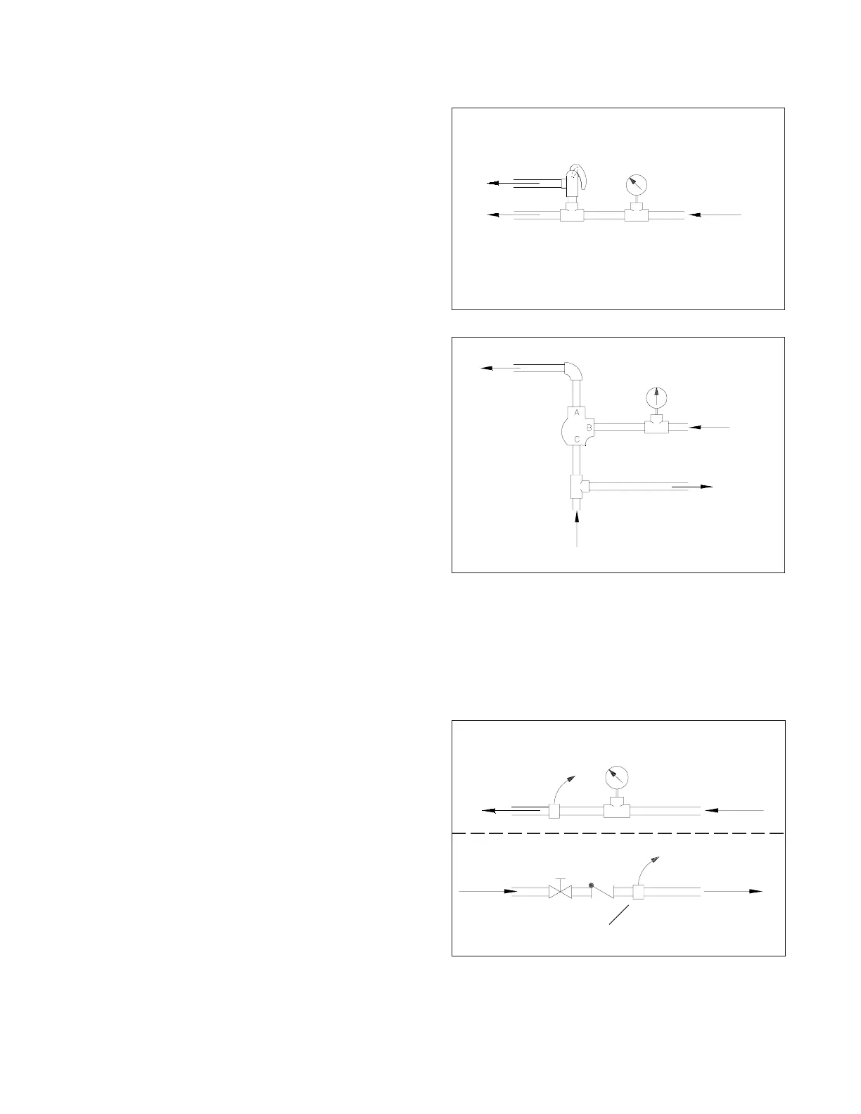
Option #1 A temperature relief valve set at roughly
15-30 degrees above that of the FLO-RITE-TEMP will help
prevent any chance of overheated water reaching the
faucets. (NOTE: Normally unit will fail closed and either no
water or only cold water will flow from the unit.)
OPTIONAL SAFETY EQUIPMENT
Option #2 A 3-way blending valve with a set point 10-
30 degrees above that of the FLO-RITE-TEMP will help
prevent the chance of overheated water reaching the faucets
in the event of unit failure. Under normal operating
conditions the hot water flows straight through the blending
valve from Port B to Port A. But in the event of an
overheated situation, the blending valve will open Port C to
add sufficient cold water to maintain a constant temperature
. (NOTE: The blending valve should be sized to handle the
maximum flow of the system).
Note: The Armstrong Flo-Rite-Temp comes supplied with a 1/4" NPT water pressure relief valve. The standard valve has a
cracking pressure of 165 psig. Installation instructions (See AY-700) are supplied with each heater. The valve is a self
relieving and slef seating valve which will open due to thermal expansion or hydrolic shock continous or intermiten
discharge of this valve while heater is in service could indicate a system pressure problem. See note for (fig. 31F) on
previous page for possible solution.
Option #3 A temperature switch installed well downstream
of the Flo-Rite-Temp outlet on a non-recirculated system or
just into the outgoing recirculated system loop on a
recirculated system, with a set point 15-30 degrees above
that of the FLO-RITE-TEMP will help prevent the chance of
overheated water reaching the faucets in the event of
system problems. This switch can be used to turn off the
steam supply to the heater in the event of overheating. The
most economical way to accomplish this is with a solenoid
on the PRV. A full ported motorized valve on the steam
supply line may also be used. Option 3B. Along these
same lines, a pressure switch installed in the inlet water line
would shut down the supply steam on the heat exchanger
in the event of water pressure loss, preventing thermal
shock and water hammer to the unit.
Option #1
Loop or System
Thermometer
Temperature
Relief Valve
Hot Water from
Flo-Rite-Temp
Option #2
Loop or System
Thermometer
3-Way
Thermostatic
Valve
Cold Water Supply
To Flo-Rite-Temp
Hot Water from
Flo-Rite-Temp
Option #3
Cold Water Supply to
Flo-Rite-Temp
Temperature
Switch
Loop or System
Thermometer
Option 3A
Option 3B
Pressure Switch
Hot Water Supply From
Flo-Rite-Temp
To Steam
Shut-Off Valve
!
To steam
shut-off valve
 Loading...