2
October 31, 2002 @ 3:15 pm
NOTICE
No water heater will work satisfactorily if improperly installed and operated. These instructions contain
important information for the installation and adjustment of the FLO-RITE-TEMP Water Heaters. Read
these instructions carefully before installing this unit. FAILURE TO ADHERE TO THESE
INSTRUCTIONS COULD RESULT IN SERIOUS BODILY INJURY OR PROPERTY DAMAGE.
STEAM PIPING INSTALLATION OF A SINGLE UNIT
FLO-RITE-TEMP
INSTANTANEOUS WATER HEATER
INSTALLATION AND ADJUSTMENT INSTRUCTIONS
NOTE: units may be piped in parallel for larger capacity requirements. See Fig. 15-1 for an example of
parallel unit installation.
The unit includes the mixing valve mounted to the heat exchanger, channel iron and U-bolts mounted,
thermostatic air vent installed on the heat exchanger, a water pressure pop off valve integral to the unit control
valve and a separate Armstrong Inverted Bucket Steam Trap.
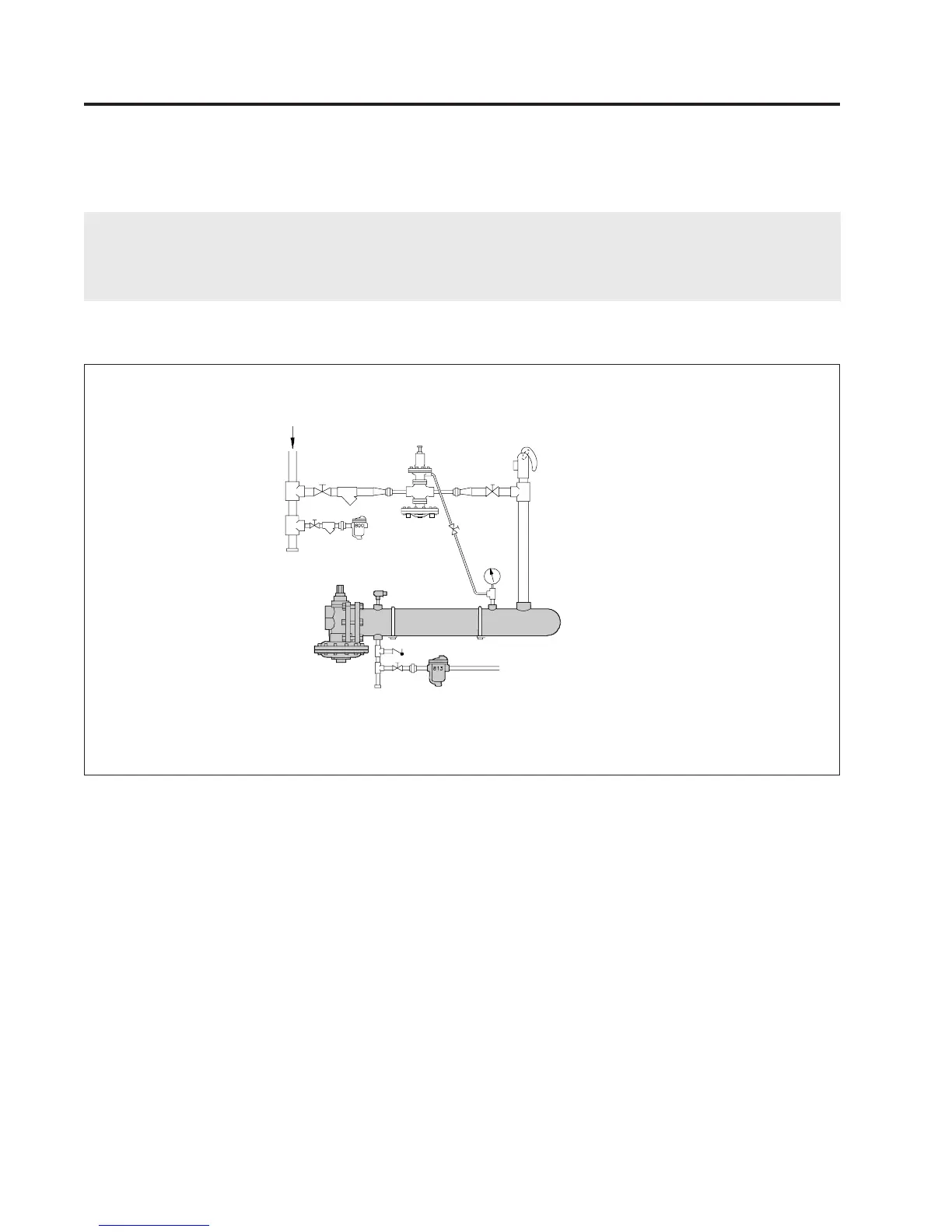
STEAM SIDE INSTALLATION
(Refer to Fig. 2-1)
1. Install the FLO-RITE-TEMP with adequate room to allow for tube bundle removal when cleaning is
required. See Table 12-1 for specific dimensions.
2. If 2-15 psig of steam is available a pressure reducing valve is NOT required. If a pressure reducing valve is
required, an Armstrong Inverted Bucket Steam Trap is recommended to drain condensate at the inlet of the
pressure reducing valve.
Fig. 2-1
NOTE: FLO-RITE TEMP is provided with (1) one Armstrong Steam Trap and Thermostatic
Air Vent (shaded). All other items shown not included.
Steam
In
Armstrong Pressure
Reducing Valve (If Req'd)
Gate
Valve
Safety Relief
Valve
GP-2000
Armstrong
I.B. Trap
Pressure
Gauge
Armstrong Thermostatic
Air Vent
2-15 psig Steam
in the Shell
Vacuum Breaker
Armstrong
I.B. Trap
Single and Double Wall