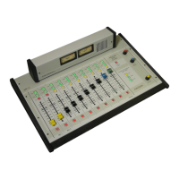
I N S T A L L A T I O N I N S T R U C TI O N S
Telephone hybrids
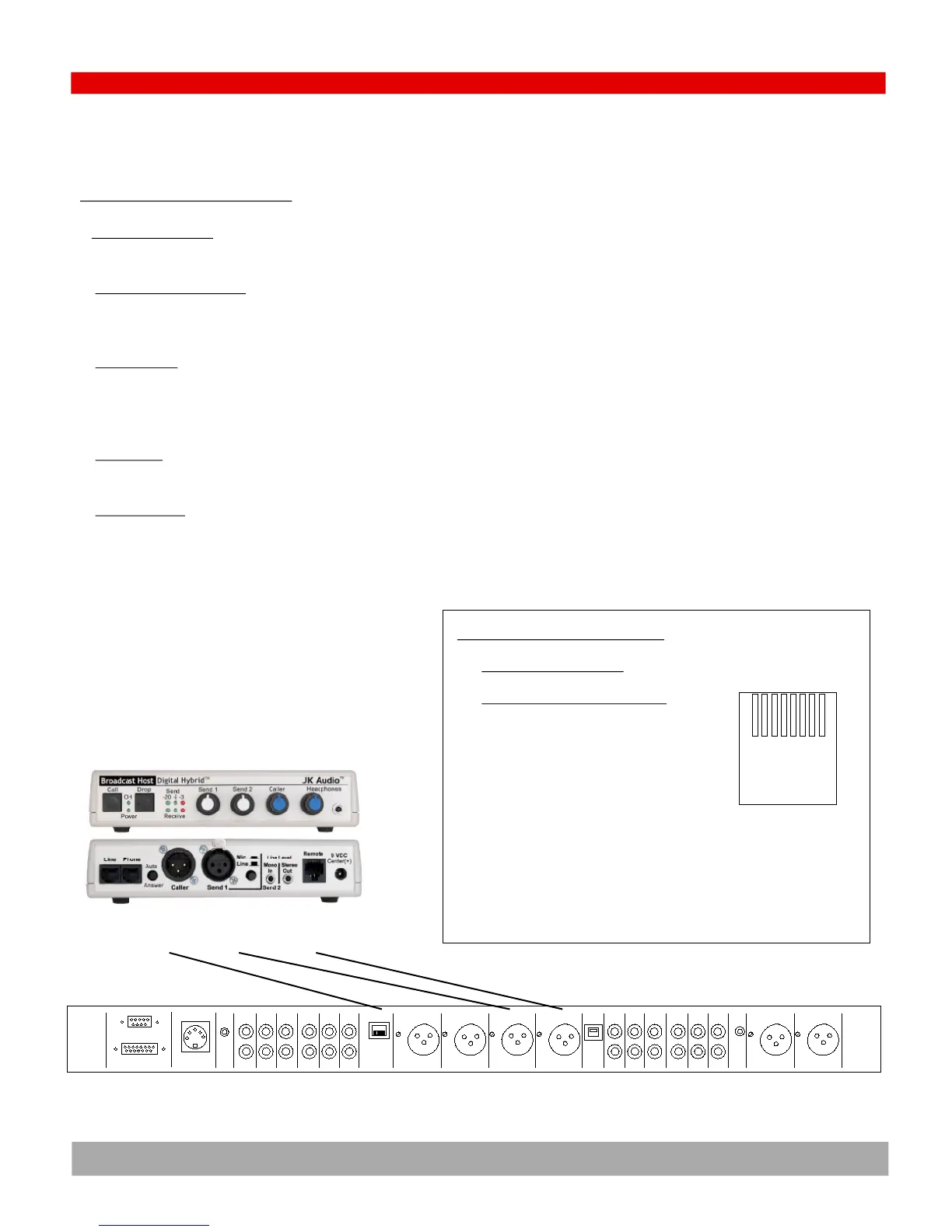
STEP 8- CONNECT A TELEPHONE HYBRID
1) CONSOLE PHONE INPUT- A telephone hybrid has an audio input and an audio output. The hybrid audio output is the callers voice and is connected to the
source input channel TEN on the console.
2) CONSOLE MIX MINUS OUTPUT
- The input to the hybrid is from the console PHONE OUT connector on the back of the console. A mix minus bus is a special
audio mixing bus that contains all audio on the console program bus MINUS the callers voice. In this way the caller hears everything except himself. If he was not
“minused” from the mix, then the caller would feed back to himself.
3) CONTROL LOGIC
- The hybrid has two ways to “answer” the caller and pick up the telephone line: front panel manual control of the hybrid itself and remote
control. For manual control, an On and Off button will be located on the front panel of the hybrid. For remote control, the PHONE LOGIC back panel connector
(RJ45) must have a custom cable connecting it to the console source start/stop logic. The logic is dry reed relay closures for both Start and Stop as shown
below.
4) CALIBRATION
- The console PHONE IN and PHONE OUT connectors are set for +4dBu levels. These connectors have trim pots next to their respective XLR con-
nectors
5) FACTORY CABLES
- Arrakis has prebuilt cables for audio and logic available for a variety of source equipment. Refer to “Factory Cables” later in this section
and on the Arrakis website (www.arrakis-systems.com)
STEP 8- CONNECT A TELEPHONE HYBRID
Audio
Input
Audio
Output
On/off
Logic
Logic
RS232
DC Power
Cue
Ch 9
In
Phone
Logic
Pgm Left Pgm Rght Phone Ch 10 Phone
Out Out Out In
PC
USB
Mic 1
In
Mic2
InIn In In In In In
Ch 8 Ch 7 Ch 6 Ch 5 Ch 4 Ch 3
48V
pwr
Ch 9
Out
Pgm
Out
Aud
AMM
PMM
Out
Mon
In
Mon
In
4.9
RJ45 WIRING STANDARD COLORS
PIN Wire Color Audio
1 White w/Orange Stripe Start w 100 ohms
2 Orange w/White Stripe Start w 100 ohms
3 White w/Green Stripe Stop w 100 ohms
4 Blue w/White Stripe Stop w 100 ohms
5 White w/Blue Stripe Start
6 Green w/White Stripe Start
7 White w/Brown Stripe Stop
8 Brown w/White Stripe Stop
1,2,3,4,5,6,7,8
RJ45
BACK PANEL HYBRID LOGIC CONNECTOR
A reed relay makes a momentary closure between the two START
contacts (pins 5 & 6) and a second reed relay makes a momentary clo-
sure between the two STOP contacts (pins 7 & 8). The same reed relays
make the same closures with a 100 ohm series resistance to Pins 1,2,3,4