I N S T A L L A T I O N I N S T R U C TI O N S
The On Air Light
STEP 11- CONNECT AN ON AIR LIGHT
The console has a logic output for triggering an external On Air Light.
This installation procedure requires a professional technician to build an interface circuit for driving the On
Air light that you have chosen. Some lights require low voltages (such as 24VDC) and others require
110VAC. Some have built in drivers but most do not.
Contact the factory for some typical circuits to drive an On Air light.
MUTING LOGIC
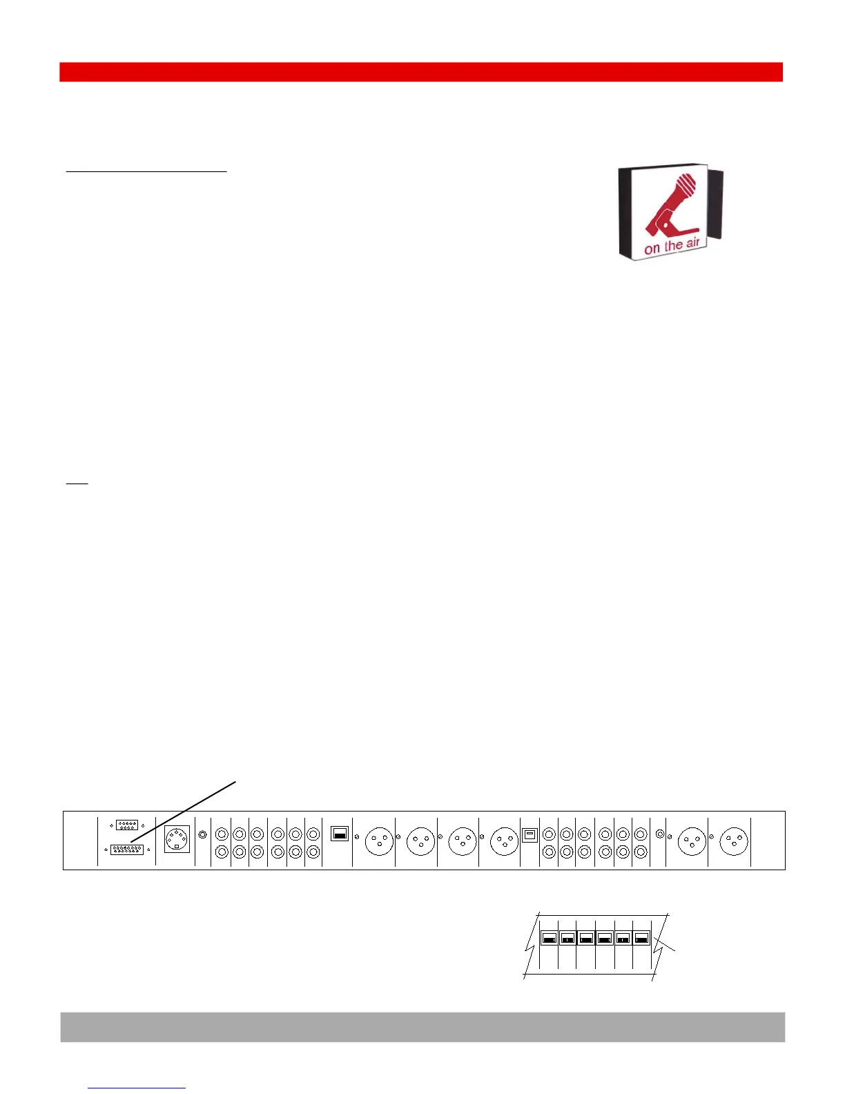
This is on PIN One of the 15 pin D-sub LOGIC connector on the rear of the console.
Muted: open collector transistor to ground, 20millamps
Unmuted: floating
IMPORTANT- The logic output will not directly drive an AC light bulb and will be destroyed if AC is applied to
any console logic pin.
TEST
Activating the On Air Light should not produce an audio pop in the console audio.
Logic
RS232
DC Power
Cue
Ch 9
In
Phone
Logic
Pgm Left Pgm Rght Phone Ch 10 Phone
Out Out Out In
PC
USB
Mic 1
In
Mic2
InIn In In In In In
Ch 8 Ch 7 Ch 6 Ch 5 Ch 4 Ch 3
48V
pwr
Ch 9
Out
Pgm
Out
Aud
AMM
PMM
Out
Mon
In
Mon
In
Back panel Diagram for ARC-10U (unbalanced base model) & ARC-10UP (unbalanced with PC model)
Ch 8 Ch 7 Ch 6 Ch 5 Ch 4 Ch 3
In In In In In In
ARC-10BP (balanced with PC model)
RJ45 balanced
audio connectors
LOGIC connector with
On Air light (Miting) logic on Pin One
4.12