I N S T A L L A T I O N I N S T R U C TI O N S
Console Logic
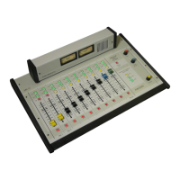
1 2 3 4 5 6 7 8
9 10 11 12 13 14 15
DB15 CONNECTOR PINOUT #1 (OLD)
CONSOLE BACK PANEL VIEW
PIN
1
2
3
4
5
6
7
8
9
10
11
12
13
14
15
DESCRIPTION
Control Room Mute Logic
Autocue Logic In
Channel Eight Logic
Channel Seven Logic
Channel Six Logic
Channel Five Logic
Channel Four Logic
Channel 3 Logic
Channel 10 Logic
Studio Monitor Left Audio
Studio Monitor Right Audio
Talkback audio from Mic 1 and Mic 2
Ground
+ 12 VDC
Audio Input to Cue for Talkback
IMPORTANT- improper connection to console logic can damage the console.
4.14
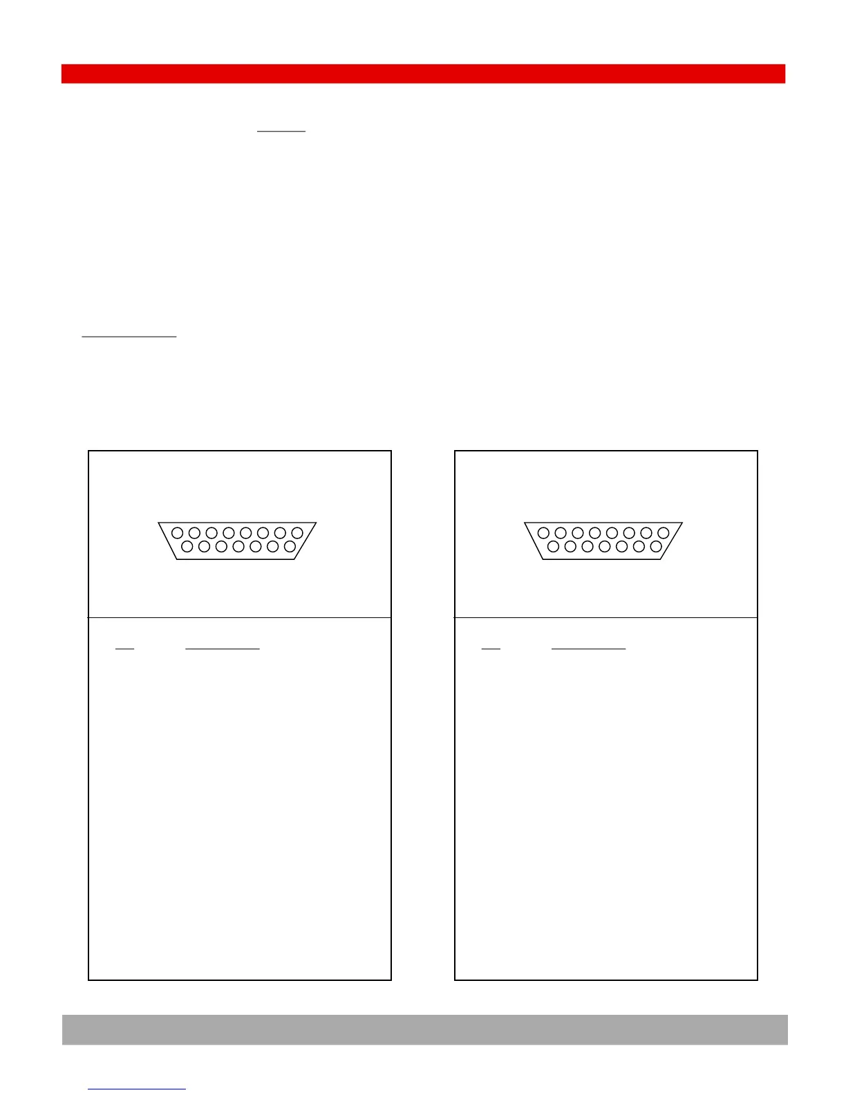
1 3 5 7 9 11 13 15
2 4 6 8 10 12 14
DB15 CONNECTOR PINOUT #2 (NEW)
CONSOLE BACK PANEL VIEW
PIN
1
2
3
4
5
6
7
8
9
10
11
12
13
14
15
DESCRIPTION
Control Room Mute Logic
Channel Ten Logic
Autocue Logic In
Studio Monitor Left Audio
Channel Eight Logic
Studio Monitor Right Audio
Channel Seven Logic
Talkback audio from Mic 1 and Mic 2
Channel Six Logic
Ground
Channel Five Logic
+ 12 VDC
Channel Four Logic
Audio INput to Cue for Talkback
Channel 3 Logic
IMPORTANT
D-sub (or DB) connectors have an old and new pin numbering convention as illustrated below.
Both conventions are provided for your convenience
The DB-15 connector on the rear panel of the console has the logic & audio signals required for support-
ing a talk studio and controlling the starting & stopping of sources.
Sample interface circuits for control are illustrated in 4.15.