S E R V I C E & M A I N T E N A N C E
General Repair Considerations
WARNING
The console should be repaired by qualified, professional, & experienced, audio technicians ONLY. Before
beginning any type of repair or opening the console CALL Arrakis customer support for recommendations.
DESIGNED FOR MODULAR PART REPLACEMENT
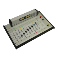
The ARC-10 console is designed for modular replacement rather than repair. The power supply is external and plug in. Most ICs are plug in. The rotary faders,
and meters are plug in. A small amount of disassembly is required to reach most parts. If the repair requires soldering to the motherboard, then the repair
should be performed at the factory. Diagrams on the following pages explain the required disassembly.
COMPONENT LEVEL REPAIR SHOULD BE PERFORMED BY THE FACTORY
Detailed schematics are not provided with the ARC-10 console because component level repair should be performed at the factory. A physical board layout is
provided with descriptions of the functions of each IC. ICs can be individually replaced to test for functionality.
POWER SUPPLY
The power supply is a sealed module that must be replaced in whole if there is a problem.
REPEATED EQUIPMENT FAILURES
If a specific part of the console is failing regularly, it is likely that it is being subject to unusual stresses.
Examples are;
(1) Switch or fader failure- rough physical treatment
(2) Mic channel IC failure- static discharge to mic
(3) Input op amp failure- lightning, power surge, or other transient on this cable
(4) Output op amp failure- lightning, power surge, or other transient on this cable
(5) Power Supply failure- lightening, power surge, or other transient on the AC power line
SUGGESTED REPAIR PROCEDURES
(1) NO AUDIO OUT OF ONE INPUT CHANNEL- (Swap Cables) Be certain that the problem is in the console itself. If mic channel two doesn’t function but mic
channel one functions properly, then plug the cable from the good mic into the channel that you suspect to be bad. If the channel that you suspect to be bad
now functions, then the problem is external to the console and is in the source or the wiring. This is a very fast and easy way to test your system.
(2) VU METERS MOVE BUT NO AUDIO OUT OF THE CONSOLE- The VU meters measure the actual output of the console itself. If the meters move but no audio
is present, the problem is after the console output and is in the following signal chain. Plug a set of headphones into the output of the console and listen to the
Program output to confirm this.
(3) LOUD LOW FREQUENCY HUM IN AUDIO-
Many years ago this would mean a power supply failure. In today’s electronics, this is an installation problem such
as a ground loop. To confirm the problem is not in the console, remove ALL wiring from the console and connect a pair of headphones to the output you are
testing. The hum should be absent. All wiring must be removed and headphones only used. A very common problem is for an audio power amp and speakers to
create the ground loop with the console.
(4) NO AUDIO OUT OF THE MONITORS
- Be certain that the monitor system is not muted due to a mic channel being on or talkback being activated.
6.1