Aud
Utl
Cue
A/B
Pgm
Line
I N S TA L L A TI O N I N S T R U C TI O N S
4.16
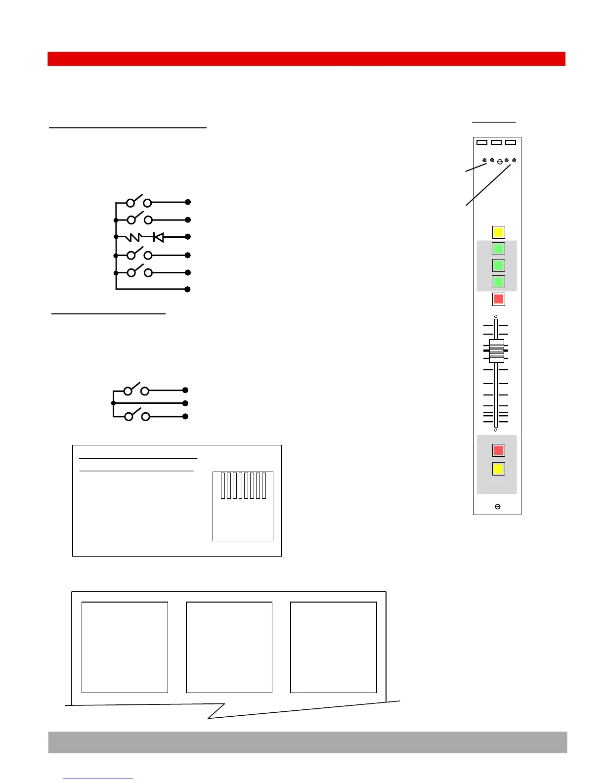
Stereo Line Level Input Module Wiring
1
2
3
4
5
6
7
8
Talk
Tally
Channel Off
Ground
Channel On
Cough
nc
nc
Logic
1
2
3
4
5
6
7
8
Left (+) in
Left (-) in
Right (+) in
Ground
nc
Right (-) in
nc
nc
‘B’ Stereo Line Input
1
2
3
4
5
6
7
8
Left (+) in
Left (-) in
Right (+) in
Ground
Stop Logic
Right (-) in
Logic common
Start Logic
‘A’ Stereo Line Input
2) Stereo Line Input module (MARC-STL)
Start logic
Common
Stop Logic
Source Control Logic
The logic controls (1) Stop Logic, (2) Start Logic, and (3) Logic com-
mon are momentary closures from a dry contact reed relay (max cur-
rent = 50 milliamps). They are available for start and stopping source
devices like CD players
‘A’
input
‘B’
input
Connectors
Logic ‘B’ ‘A’
PIN Wire Color Audio
1 White w/Orange Stripe Left (+)
2 Orange w/White Stripe Left (-)
3 White w/Green Stripe Right (+)
4 Blue w/White Stripe Ground
5 White w/Blue Stripe
6 Green w/White Stripe Right (-)
7 White w/Brown Stripe
8 Brown w/White Stripe
1,2,3,4,5,6,7,8
RJ45
EIA/TIA 568B WIRING STANDARD COLORS
Channel Control Logic (Turrets)
The pins on the ‘Logic’ connector are used to remote control the mod-
ule for applications such as studio talk turrets. Controls include Chan-
nel On, Off, Tally LED driver for on-off status, Talk to Console, and
momentary Cough logic. All control is by dry closure to ground. The
tally LED should be connected through a 510 ohm resistor to ground.
Channel On
Channel Off
On-off Tally LED
Talk to Console
Cough
Ground

 Loading...