I N S TA L L A TI O N I N S T R U C TI O N S
The PC-USB input Module Wiring
4.17
1
2
3
4
5
6
7
8
Record Logic
Ch On-off logic
Ground
Ground
nc
nc
nc
nc
RS232 Logic
1
2
3
4
5
6
7
8
Left (+) in
Left (-) in
Right (+) in
Ground
nc
Right (-) in
nc
nc
Record Input
USB Connector
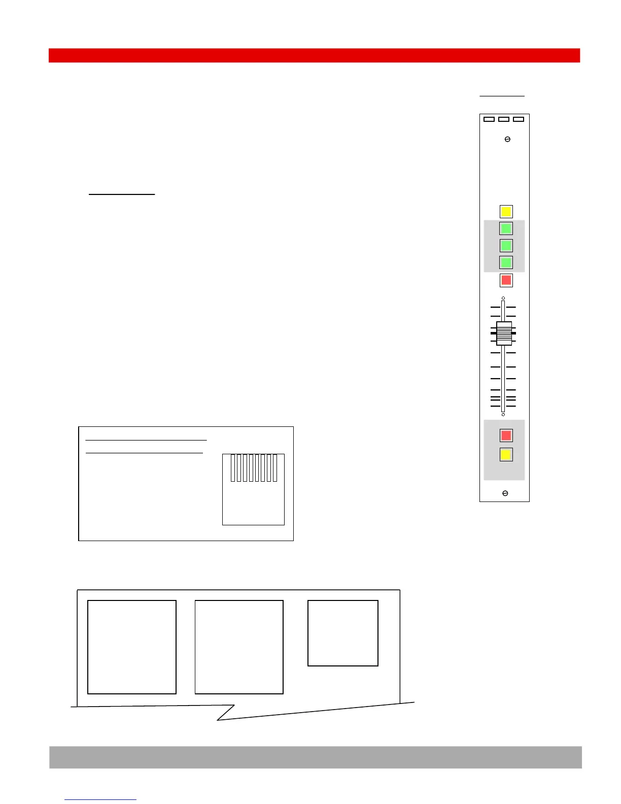
4) PC USB module (MARC-USB)
The RJ45 connector titled ‘RS232 Logic’ wires to a 9 pin RS232 D-sub con-
nector as illustrated below
9 Pin RS232
1 nc
2 Pin 1 RJ45
3 nc
4 nc
5 nc
6 Pin 2 RJ45
7 nc
8 nc
9 Pin 3 RJ45
Connectors
Logic Rec USB
Aud
Utl
Cue
Rec
ord
Pgm
PC USB
PIN Wire Color Audio
1 White w/Orange Stripe Left (+)
2 Orange w/White Stripe Left (-)
3 White w/Green Stripe Right (+)
4 Blue w/White Stripe Ground
5 White w/Blue Stripe
6 Green w/White Stripe Right (-)
7 White w/Brown Stripe
8 Brown w/White Stripe
1,2,3,4,5,6,7,8
RJ45
EIA/TIA 568B WIRING STANDARD COLORS

 Loading...