C
hapter
Ⅳ
P
rogramming on
FAB
panel
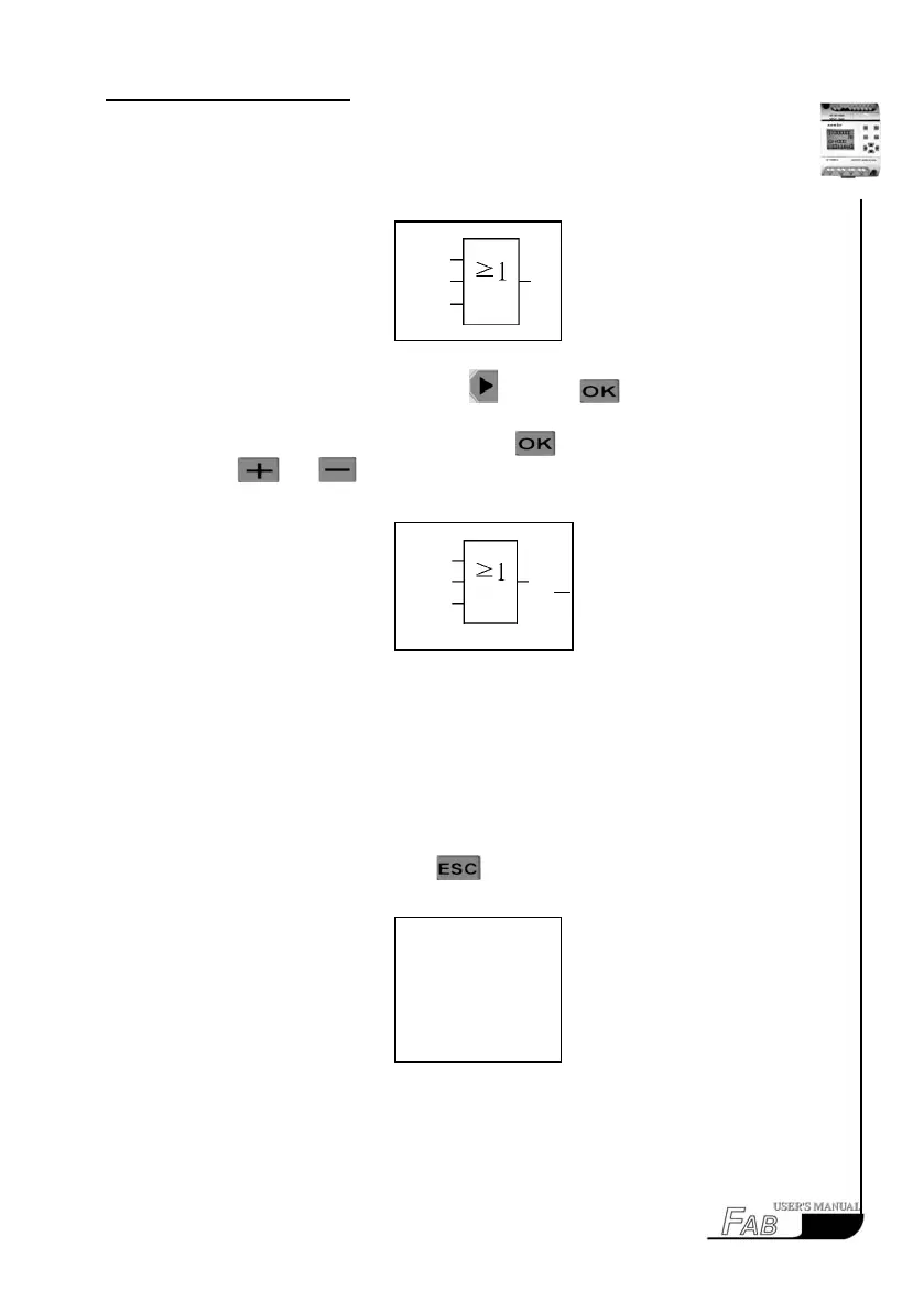
The following will be on the LCD panel:
Fig. 4.43
Move the cursor to the output link with and press .
After selecting Q in the parameter list, press
and set the said output Pin to
be Q1 with
and . Then the following will be displayed on the LCD
panel:
Fig. 4.44
Now all the three function blocks required for the editing of this function dia-
gram are selected and set, which means that the Function Diagram is completely
edited.
Step 3: Run
1. After Step 2 is finished, press
twice consecutively to return to the
Select Function Selection. The following will be displayed on the LCD panel:
Fig. 4.45
63
M01
X
M02
B03
B03
M01
X
M02
Q01
>Editor
FAB/Rom
Set..
RUN