EasyManua.ls Logo

Artec Robo 2.0 - User Manual

Artec Robo 2.0
12 pages
Print Icon
To Next Page IconTo Next Page
Loading...
1
TheCoreUnitisthepartoftherobotthatrunsprograms.
PartsoftheCoreUnit
1
⑤5x5FullColorLEDMatrix
TheseLEDslightupinRGBcolorstodisplayvariousimages.
⑨Buzzer
Transformselectricalsignalsintosound.
①TemperatureSensor
⑥LightSensor
Thissensorusesaphototransistorthatconvertslightinto
electricitytomeasuretheintensityofsurroundinglight.
②/③A/BButtons 
TheCoreUnitdetectswhenthesebuttonsarepressed.
④PowerLight(Green)
Thislightturnsonwhenthepowerison.
⑦ConnectionLight(Blue)
Thislightturnsonwhenwirelesscommunications
(throughBluetooth/Wi-Fi)areoccurring.
⑧ArtecBlockConnectingCover
Thiscovercanbeattachedtotheedgeconnector.
IthasstudsonitthatcanbeusedtoconnecttoArtecBlocks.
Thissensormeasuresexternaltemperature.★TheinternaltemperatureoftheCore
Unitmayaffectthereadingsofthetemperaturesensorifitbecomesheatedbyextend-
eduseofsignificantelectricalpower,forinstanceusingtheLEDmatrix.
(Back)(Front)
Instructions
⑩9-AxisSensor
⑫USBPort(microB)
⑬ResetButton
Thisbuttonisusedtorestartthedevice.
⑭PowerConnector
AportusedtoplugaBatteryBoxintothedevicetosupply
power.
⑪EdgeConnector
Aconnectorforexternalexpansiondevices.
3-AxisAccelerometer:Quantifiesthedevice'smotionandtilt
bymeasuringacceleration.
3-Axis Gyroscope: Measures angular velocity to quantify
rotationalmotionstheaccelerometercan'tdetect.
3-AxisCompass:Quantifieswhichwaythedeviceisfacingby
measuringtheEarth'smagneticfield.
AportusedtoplugUSBcablesintothedevicetotransfer
programsfromacomputerorsupplypower.
(Top)
●Thesematerialsarenotdesignedforchildrenunder8yearsofage.Childrenunder8should
onlyusethesematerialswithadultsupervision.
●Pleaseseeanymanualortextbookincludedwiththeproductforinstructionsonsafe
assemblyanduse.Makesuretofollowcableconnectioninstructionstoavoiddamageor
injuryfromincorrectassembly.
●Thisproductisnotedible.Donotputanypartsofthisproductintoyourmouthtoprevent
accidentalingestion.
●Donotwrapcordsorcablesaroundyourhands,fingers,neck,etc.Donotpluganycables
intohouseholdoutlets,oryoumayreceiveanelectricshock.
●Toavoidinjury,donottouchtherotatingpartsofthemotorswhenthepoweristurnedon.
●ShouldtheCoreUnit,motororBatteryBoxbecomeveryhot,immediatelyturnoffthe
powerandceasehandlingthedevice.
●BeawarethatusingthemotororCoreUnitundercertainconditions
(improperhandling,
excessiveload,extremetemperatures)
maycauseittooverheat,andtakecaretoavoidburns.
●BesurethatthemotionoftheincludedDCMotor'saxleisnotobstructedwhenthemotor
ispowered.Evenbriefobstructionmaycauseburningdependingontheconditionofthe
motor.
●Somepartshavesharpedges,sohandlewithcare.
●Donotleavepartslyingonthefloor,astheymaycauseinjuryifsteppedon.
●Becarefulnottogetfingerspinchedbetweenmovableparts.
●Donotsubjecttheproducttostrongimpacts,setheavyobjectsontopofit,etc.
●Foryoursafety,avoidusingpartsthathavebeendamaged.
●Whennotinuse,shutoffallpowertotheproductandstoreoutofreachofsmall
children.
Improperbatteryusagemayresultinoverheating,rupture,orleakage,sotakenoteofthe
followingwhenusingbatteries:
●Donotusenon-alkalinebatteries.Rechargeablebatteriesinparticularareknownto
causeproblems,sodonotusethem.
●Batteriesaretobeinsertedwithcorrectpolarity.
●Donotmixoldandnewordifferentkindsofbatteries.
●Donotattempttoshortcircuit,recharge,disassemble,orheatbatteries.Donotinsert
batteriesintofire.
●Ifitwillbeoutofuseforanextendedperiodoftime,removethebatteriesfromthe
batterybox.
●Ifbatteryleakageoccursandanybatteryfluidgetsintotheeyes,immediatelyflushwith
waterandseekmedicaltreatment.Iffluidcomesintocontactwithskinorclothes,wash
immediatelywithwater.
Warning
 
CHOKINGHAZARD-Smallparts.Thisproductcontainschokinghazardsandisnotsuitableforchildrenundertheageof3.
WARNING
Makesuretoreadtheseinstructionscarefullybeforeassemblyoruseofthesematerials.
         (Parents/Guardians:besuretoreadtheinstructionsandensurechildrenreadthemaswell.)
ArtecRobo
Question and Answer IconNeed help?

Do you have a question about the Artec Robo 2.0 and is the answer not in the manual?

Summary

Parts of the Core Unit

Core Unit Sensors

Includes Temperature, Light, and 9-Axis sensors for environmental and motion data.

Core Unit Indicators and Input

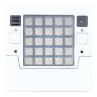
Features Power/Connection lights, A/B buttons, and a Buzzer for user feedback and interaction.

Core Unit Connectivity and Control

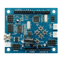
Includes Edge connector, USB port, Reset, and Power connectors for expansion and operation.

Artec Block Connecting Cover

Cover for edge connector with studs for connecting Artec Blocks.

Functions of Each Edge Connector Pin

Using the Battery Box

Starting the Core Unit

Connect the Power

Connect Battery Box or USB cable to turn on the device.

Enter Program Select Mode

Enter program selection mode by holding A and pressing reset.

Select and Start Programs

Select and run programs using A and B buttons.

Turn Off the Power

Disconnect Battery Box or USB cable to turn off the device.

Running the Sample Programs

Using Artec Blocks

Connecting Artec Blocks

Understand stud placement and pull blocks straight apart to connect/disconnect.

Using the Block Remover

Step-by-step guide on using the Block Remover tool for separating blocks.

The Robot Expansion Unit

Power and Connector Ports

Details on Power Switch, Power Connector, and DC Motor Terminals (M1/M2).

Expansion Unit Terminals

Explains Digital Output, Analog Input, and I2C Communication terminals.

Connector Usage Notes

Guidance on polarized ports, non-reversible plugs, and cable compatibility.

Parts Compatible with the Robot Expansion Unit

LEDs and Buzzers

Compatibility of LEDs (white, blue, green, red) and Buzzers with expansion unit terminals.

Servomotors

Connecting Servomotors to digital output terminals, including default angles and rotation.

DC Motors and Sensors

DC Motors

Connecting DC Motors to terminals, speed control, and external power requirements.

Touch Sensors

Connecting Touch Sensors to analog input terminals for ON/OFF detection.

Sound Sensors

Connecting Sound Sensors to analog input terminals for audio detection.

Light Sensors

Connecting Light Sensors to analog input terminals for measuring light intensity.

Accelerometers

Connecting Accelerometers to I2C terminal for slope and movement data.

IR Photoreflectors and Cables

IR Photoreflectors

Connecting IR Photoreflectors to analog input terminals and how they work.

Sensor Connecting Cables

Details on 3-wire and 4-wire sensor connecting cables and their uses.

Software Instructions

Overview

The ArTec Robo 2.0 is a programmable robot designed for educational and creative use, featuring a Core Unit that serves as the central processing component. This device allows users to build and program robots using a variety of sensors, actuators, and structural blocks.

Core Unit

The Core Unit is the brain of the robot, running all programs and managing interactions with connected components. It features a 5x5 full-color LED matrix for visual feedback, displaying various images and information in RGB colors. For user input, it includes two A/B buttons, which are detected when pressed, allowing for interactive control and program selection.

Environmental sensing capabilities are integrated directly into the Core Unit. A temperature sensor measures external temperature, though users should be aware that the internal temperature of the Core Unit itself can affect readings, especially during extended use with significant electrical power, such as when the LED matrix is active. A light sensor, utilizing a photo transistor, converts ambient light into electricity to measure surrounding light intensity. For auditory feedback, a buzzer transforms electrical signals into sound.

Motion and orientation are detected by a 9-axis sensor, which includes a 3-axis accelerometer to quantify motion and tilt, a 3-axis gyroscope to measure angular velocity and rotational motions, and a 3-axis compass to determine the device's facing direction by measuring Earth's magnetic field.

For connectivity and expansion, the Core Unit is equipped with an edge connector for external expansion devices, a microB USB port for transferring programs from a computer and supplying power, and a power connector for plugging in a Battery Box. A reset button is also present to restart the device. Wireless communication is supported, indicated by a blue connection light that illuminates during Bluetooth/Wi-Fi activity. An Artec Block connecting cover with studs allows for direct attachment of Artec Blocks.

Usage Features of the Core Unit

To start the Core Unit, users can connect either a Battery Box or a USB cable. The device automatically switches on, and a green power light illuminates. For program selection, users hold down the A button and press the reset button. After the power light briefly turns off and then back on (approximately 3 seconds after releasing the reset button), releasing the A button will put the device into Program Select Mode, indicated by a '0' displayed in green LEDs. In this mode, pressing the A button cycles through program numbers (0-9), and pressing the B button runs the selected program.

The device comes pre-loaded with sample programs for testing. These include:

  • Adjustable Light: All display LEDs turn on. The A button adjusts brightness, and the B button changes color.
  • Night Light: Covering the light sensor makes the LEDs light up.
  • Thermometer: The current temperature scrolls across the display.
  • Rolling Light: Tilting the device moves the light position on the display, controlled by the accelerometer.
  • Turntable: Spinning the device reverses or changes the speed of a playing song.
  • Compass: Displays an arrow pointing north. Requires calibration by rotating the Core Unit until all outer border LEDs are illuminated.
  • Current Tester: The buzzer produces sounds based on electrical resistance between GND and 0-2 points on the edge connector.
  • Light Game: Users press A and B buttons to move a green light left and right, avoiding falling red lights.
  • Wi-Fi Connection Checker: Displays the current MAC address, allowing users to confirm Wi-Fi connection on other devices.

Downloading new programs from the software overwrites existing sample programs in the selected slot. To turn off the device, users simply disconnect the Battery Box and/or USB cable. The next standard start-up will run the last selected program.

Artec Blocks

Artec Blocks are structural components with a special shape that requires attention to stud position during building. They are designed to be pulled straight apart for disassembly; forcing them to bend may cause damage. For difficult separations, a Block Remover tool can be used: insert the upper part of the remover into the gap between blocks, slide it, and pull. The claws of the remover can also pinch the base of a block to create a gap, followed by pulling the block out.

Robot Expansion Unit

The Robot Expansion Unit expands the Core Unit's capabilities by adding more motors and sensors. The Core Unit can be connected to the expansion unit in either direction.

Usage Features of the Robot Expansion Unit

The expansion unit includes a power switch to turn the Core Unit's power ON/OFF by holding it for approximately 2 seconds. A power connector (marked BATT) is available for plugging in a Battery Box, and it is crucial for supplying power when using Servomotors or DC Motors with the expansion unit.

The unit provides several types of terminals:

  • Digital Output Terminals (P13/P14/P15/P16): For connecting LEDs, Buzzers, and Servomotors.
  • DC Motor Terminals (M1/M2): For connecting DC Motors.
  • Analog Input Terminals (P0/P1/P2): For connecting various analog sensors.
  • I2C Communication Terminal: For sensors that use I2C buses, such as Accelerometers.

All ports on the expansion unit are polarized, using nonreversible plugs. Users must ensure the plug faces the correct way when connecting. Original Artec Robo parts can be connected, but their connecting cables for sensors and Servomotors do not have nonreversible plugs. When connecting, users should align the wire colors with the matching marks above the port. Note that Artec Robo's 4-wire sensor connecting cable (for Accelerometers) is not compatible with this unit.

Compatible Parts with the Robot Expansion Unit

  • LEDs: Available in white, blue, green, and red, distinguishable by writing on their circuit boards. They connect to digital output terminals (P13/P14/P15/P16) with a 3-wire sensor connecting cable.
  • Buzzers: Transform electric signals into sound. They can be confused with IR Photoreflectors, so users should check the circuit board label. They connect to digital output terminals (P13/P14/P15/P16) with a 3-wire sensor connecting cable. The device can control up to four buzzers, including the Core Unit's internal buzzer.
  • Servomotors: Motors that turn to precise angles (0-180°, with a default of 90°). The rotational direction is printed on the servomotor. They connect to digital output terminals (P13/P14/P15/P16). When using servomotors, care should be taken not to confuse blocks directly attached to the motor with those connected by a screw.
  • DC Motors: Their speed and duration of rotation can be changed by adjusting the amount and length of electricity supplied. They connect to DC Motor terminals (M1/M2). DC Motors require external power even when the device is powered via USB.
    • DC Motor Slip: Motors are designed to "slip" (emit clicks and turn freely) under excessive strain to prevent gear damage. If this occurs, users should inspect the motor and fix the strain. Continuous slipping reduces the amount of strain required for future slips.
  • Touch Sensors: Physical sensors with a button. They read as ON when pressed and OFF when not. They connect to analog input terminals (P0/P1/P2) with a 3-wire sensor connecting cable.
  • Sound Sensors: Use a condenser microphone to pick up sound; louder sounds result in higher sensor values. They connect to analog input terminals (P0/P1/P2) with a 3-wire sensor connecting cable.
  • Light Sensors: Use a phototransistor to convert light into electricity, measuring intensity. Brighter light yields higher values. They resemble LEDs but are distinguishable by their black circuit board and label. They connect to analog input terminals (P0/P1/P2) with a 3-wire sensor connecting cable.
  • Accelerometers: Convert changes in slope and movement into numerical values. They connect to the I2C communication terminal with a 4-wire sensor connecting cable.
  • IR Photoreflectors: Emit invisible infrared light and detect reflected light, converting it to a numeric value (closer objects yield higher values, though objects too close may not be detected). Object color can also affect reflection. They can be confused with Buzzers, so users should check the circuit board label. They connect to analog input terminals (P0/P1/P2) with a 3-wire sensor connecting cable. Natural light contains detectable infrared light, which can affect sensor values depending on the environment.

Maintenance Features

  • Battery Usage: The Battery Box uses three AA alkaline batteries, which must be inserted with correct polarity. Non-alkaline and rechargeable batteries are not recommended. Old and new batteries, or different kinds of batteries, should not be mixed. Batteries should be removed if the device will be unused for an extended period.
  • Safety: Users should avoid short-circuiting, recharging, disassembling, or heating batteries, and never insert them into fire. In case of battery leakage, eyes should be flushed with water and medical treatment sought; skin or clothes in contact with fluid should be washed immediately.
  • General Device Care: Avoid strong impacts, placing heavy objects on the device, or touching rotating motor parts when power is on. If the Core Unit, motor, or Battery Box becomes very hot, power should be immediately turned off. The DC Motor's axle should not be obstructed when powered, as even brief obstruction can cause burning. Some parts have sharp edges and should be handled with care. Parts should not be left on the floor to prevent injury. Fingers should be kept clear of movable parts to avoid pinching. When not in use, all power should be shut off, and the product stored out of reach of small children.
  • Cable Management: Cords and cables should not be wrapped around hands, fingers, or neck. Cables should not be plugged into household outlets to avoid electric shock.
  • Ingestion Prevention: The product is not edible, and parts should not be put into the mouth.
  • Age Appropriateness: The materials are not designed for children under 8 years of age; children under 8 should use them only with adult supervision.

Software Instructions

Instructions for using the software are available on the Artec Robo 2.0 software download page at https://www.artec-kk.co.jp/artecrobo2/.

Artec Robo 2.0 Specifications

General IconGeneral
CategoryEducational Robotics Kit
Programming LanguageScratch
ConnectivityUSB
SensorsLight sensor, Touch sensor
ActuatorsDC Motors
Componentssensors, motors, wheels
Power Source6 x AA Batteries

Related product manuals