571-0406 Rev. M Company Confidential 1
ARTEX PRODUCTS / ACR ELECTRONICS, INC.
5757 Ravenswood Rd, Ft. Lauderdale, FL 33312
Cage Code: 18560
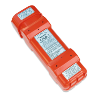
406 SERIES ELTs
INSTALLATION INSTRUCTIONS FOR ARTEX AIRCRAFT SUPPLIES, INC. BATTERY
PACK PART NUMBER 452-0131, 452-0133, & 452-0222
The battery pack must be replaced on or before the expiration date shown on the
battery label.
A yearly inspection is highly recommended. A detailed procedure is included in the 406 Series
ELT Installation and Operation Manual. To install a fresh
battery pack, follow the step by step
instructions below:
1.
Disconnect the antenna leads and remote control wire harness.
2.
Remove the ELT from its mount.
3.
Remove the battery pack from the ELT (four screws).
4.
Remove the battery connectors (one 8 pin and one 2 pin connector).
5.
Inspect ELT for damage to the case, O-Ring, and electrical connections. Reject ELT if found.
6.
Remove paper backing from foam strip on battery pack and apply silicone grease.
DO NOT USE PETROLEUM BASED GREASE.
7.
Check the gasket to ensure it is in the groove and not exposed to pinching when battery
is
installed.
8.
Install the new battery pack by reconnecting the 8-pin connector to the header on the circuit
board First, and then connect the 2-pin harness to the ELT. Check to ensure the gasket is not
susceptible
to being pinched when battery is rolled over into position.
CAUTION: If the above step is not completed as written, the connection may cause the fuse on
the battery board to blow! Ensure the connection sequence is done correctly as described
above.
NOTE: This step will cause the ELT to activate. Reset the ELT by toggling the
ON/OFF switch on the ELT to the “ON” position and then back to the “OFF” position.
Replace the four screws. Tighten screws per pattern in DETAIL A. Ensure that the O-
rings are still installed around the screws. Apply a 7 to 9 in-lb. torque on the
screws. Check the gap between the battery pack and H-Shield to ensure it is
uniform.
9.
Affix the supplied expiration date placard to the ELT Mounting Cap as shown.
10.
Reinstall the ELT in its assembly an d mount securely. Connect the antenna leads and remote
control
wire harness.
11.
Place the manual switch in the “ON” position and monitor the ELT’s operation with a
communication receiver tuned to 121.5 MHz. If the ELT can be heard, move the switch
back to
the “OFF” or “ARMED” position. Verify that there is no 7-flash error code
displayed on the
local LED; see applicable ELT Manual for details on testing ELT.
12.
Enter in the airframe logbook the date of the installation of the new battery pack and the
next
replacement date. The sticker enclosed with battery pack can be used for this
purpose.
13.
Do not discard the old battery pack in fire or flame. Dispose of the battery pack as per
local
environmental regulations.
13 Page 2 contains an expanded view of a 406 Series ELT assembly, showing
the battery pack and
ELT assembly.