Do you have a question about the ARTEX DGL-1 and is the answer not in the manual?
Describes the operation, installation, and maintenance of the DGL-1 Dongle Programming Adapter for continued airworthiness.
Details the supporting data for the Dongle, including description, operation, test, removal, installation, registration, and parts list.
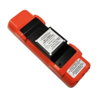
Details the DGL-1 as a 24-bit address programming adapter with DIP switches, attached to an ELT top cover for fleet operators.
Lists the FAA TSO-C126 and ETSO 2C126 system component approvals for the Dongle DGL-1.
Lists US regulatory documents like AC 43-210, AC 43.9-1, AC 43-13-1/2, and COSPAS-SARSAT guidelines.
Lists other available documents, such as the ELT Test Set (ETS) Operation Manual, accessible online or by request.
Explains the Dongle's function to program aircraft 24-bit address into a compatible ELT, verifying or programming the address.
Describes the Dongle's design for mounting to an ELT top cover using screws or directly to the airframe via a cable assembly.
Highlights the Dongle's capability to reprogram ELTs with 24-bit address location protocol programming, with a caution on aircraft labeling.
Details the Dongle's automatic operation requiring only +28 VDC power and specific ELT conditions for functionality.
Lists the electrical specifications of the Dongle, including pin functions, voltage, and software compatibility.
Presents the physical specifications of the Dongle, including weight and dimensions when mounted on an ELT top cover.
Covers inspection, testing, and fault isolation procedures specific to the Dongle and its integration with the ELT system.
Details the periodic inspection of the Dongle, including visual checks for damage, corrosion, wear, and cracks.
Outlines test procedures including 24-bit address programming verification and 15-digit hex ID determination.
Provides a troubleshooting guide for installation and operational issues, detailing symptoms, probable causes, and possible solutions.
Details the sequence for removing the Dongle from the ELT, including disconnecting the connector and removing screws.
Lists required information for returning material or equipment to the factory, such as model, serial number, and failure cause.
Explains the process of obtaining an RMA number from ACR Electronics for returning material or equipment.
Outlines regulatory requirements and guidelines for ELT installations, applicable to the DGL-1 Dongle Programming Adapter.
Details FAA requirements, including AC 43.9-1, AC 43-210, and FAR Part 43, for supporting field approval.
Specifies that installations must comply with Canadian Aviation Regulations (CAR) Part V.
States that installations outside the US and Canada must follow applicable national regulatory rules.
Provides guidance on selecting the Dongle location, cautioning against exposure to chemical fluids.
Describes how to mount the Dongle on the ELT top cover using screws and coordinate with ELT installation.
Covers wiring and grounding considerations, including wire size, shielding, drip loops, and grounds.
Illustrates the Dongle wiring harness arrangement and the Molex 12-pin connector harness.
Details the Molex 12-pin connector harness arrangement, mentioning disassembly and extraction tools.
Explains connecting power and ground wires, emphasizing not wiring directly to the battery and using a fuse/breaker.
Explains the 24-bit address composition, encoding via switch block, and the reprogramming process.
Provides guidance on converting octal or hexadecimal aircraft IDs to the required 24-bit binary address.
Details how to set the 24-bit address switch block based on the determined binary code for programming.
Explains the purpose of the illustrated parts list and how to use the IPL for identifying and ordering parts.
Provides contact information for ACR Electronics and details on how to order approved parts.
Explains the nomenclature column, including indenture system, service bulletin annotations, and part interchangeability terms.
Describes the part number column which contains the manufacturer's part number for each item.
Lists the parts for the DGL-1 Programming Adapter Assembly, including the main unit and attaching parts.
Lists the parts for the wire harness, including the install kit, terminals, labels, and splices.
| Output Voltage | 12V DC |
|---|---|
| Output Current | 1A |
| Material | Plastic |
| Color | Black |
| Input Voltage | 100-240V AC |
| Weight | 100g |