ARTEX PRODUCTS / ACR ELECTRONICS, INC.
DESCRIPTION, OPERATION, INSTALLATION AND MAINTENANCE MANUAL
DGL-1, DONGLE (453-4010)
570-4010 Rev. G Company Confidential Page 22 of 30
B. Dongle Wiring
1) Refer to Figure 8 Dongle Wiring Diagram on page 24.
2) Refer to the applicable ELT Description, Operation, Installation & Maintenance Manual for pin
configuration and additional wiring information.
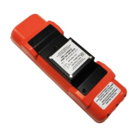
Figure 5 Dongle Wiring Harness Arrangement
3) A preassembled wire harness (P/N 611-4010) is provided with the Dongle.
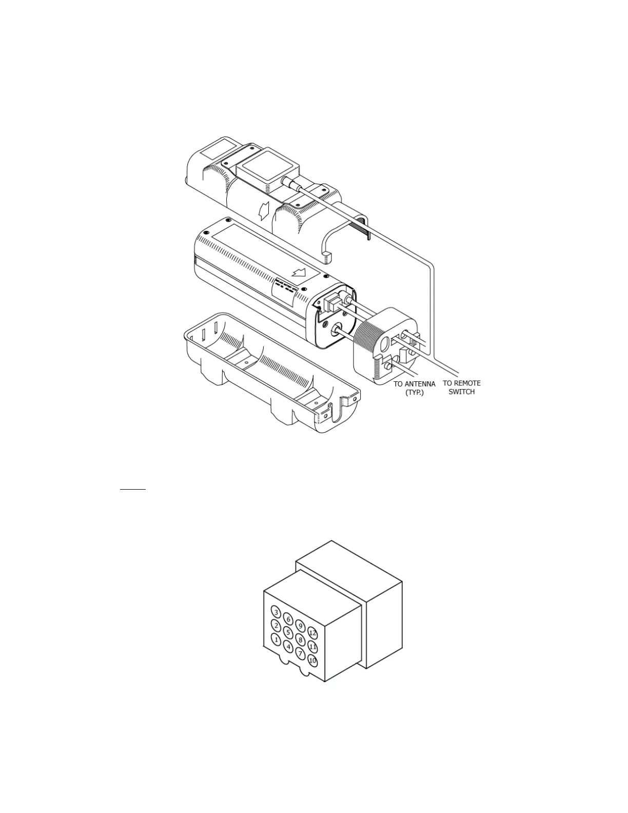
NOTE: Disassembly of the 12 position rectangular connector is required when installing a
Dongle on an aircraft previously equipped with an ARTEX ELT to integrate the wire
harness. Refer to Figure 6 Molex 12-Pin Connector Harness Arrangement on page 22.
Use Molex extraction tool (Molex P/N 11-03-0002), or an equivalent tool for 0.062 in.
terminal pins.
Figure 6 Molex 12-Pin Connector Harness Arrangement
4) Assemble the wire harness with the Dongle wire harness (P/N 611-4010). See Figure 8 Dongle Wiring
Diagram on page 24.