Follow Wiring Diagram
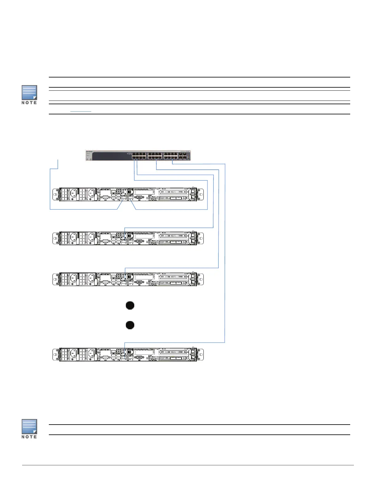
Use the following steps to connect the Analyzer appliances:
1. Connect ETH0 of AN Node to the corporate network. The Analyzer UI can be accessed from this network.
2. Connect ETH1 of AN Node to any port on the 10G switch.
3. Connect ETH0 of each Compute Node to any port on the 10G switch.
Use ethernet cables capable of 10G speeds.
All the ports on the 10G switch serve the same purpose. It does not matter which ones are used.
Refer to Figure 4 for a detailed back view of the appliance as you connect the cables in the wiring diagram.
Figure 5 Wiring Diagram for Analyzer Models AI-ANA-1000-AN, AI-ANA-1000-CN, AI-ANA-1500-AN, AI-ANA-
1500-CN with Copper Management Port
Compute Node N
Compute Node 2
Compute Node 1
AN Node
ETH0 ETH1
ETH0
ETH0
ETH0
24 Port 10G Switch – Part # JZ273A
To
Corporate
Network
Configure the Analyzer Cluster
1. Connect a laptop to a free port on the 10G switch.
2. Open a browser instance and connect to: https://192.168.1.254:8443.
3. Complete the IntroSpect setup wizard.
For detailed setup instructions, see the IntroSpect Appliance Setup Guide.
4 IntroSpect Analyzer 1XXX Series | Quick Start Guide
 Loading...