2 Aruba 203R Series Wireless Access Points | Installation Guide
LED
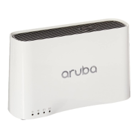
The LED displays located on the front panel of the access point indicate the following functions:
System Status
The System Status LED indicates the operating condition of the access point, See Table 1.
1 Blinking: one second on/one second off.
2 Flashing: on/off repeated in less than 1s
Radio Status
The Radio Status LED indicates the operating mode of the access point’s radios. See Table 2.
Table 2 Radio Status LED
3 Alternating: light cycles alternate between green/amber; one second on/one second off.
Table 1 System Status LED
Color/State Meaning
Off Device is powered off
Green/solid Device is ready; fully functional
Green/blinking
1
Device is booting; not ready
Green/flashing
2
Device is ready; uplink negotiated at suboptimal speed (<1Gbps)
Red/solid Error condition
Color/State Meaning
Off Meets one of the following conditions:
Device is powered off
both radios are disabled
device is powered off
Green/solid Both radios enabled in access mode
Green/blinking One radio enabled in access mode; one radio disabled
Amber/solid Both radios enabled in monitor mode
Amber/blinking One radio enabled in monitor mode; one radio disabled
Alternating
3
One radio enabled in access mode; one radio in monitor mode

 Loading...