4 Aruba 203R Series Wireless Access Points | Installation Guide
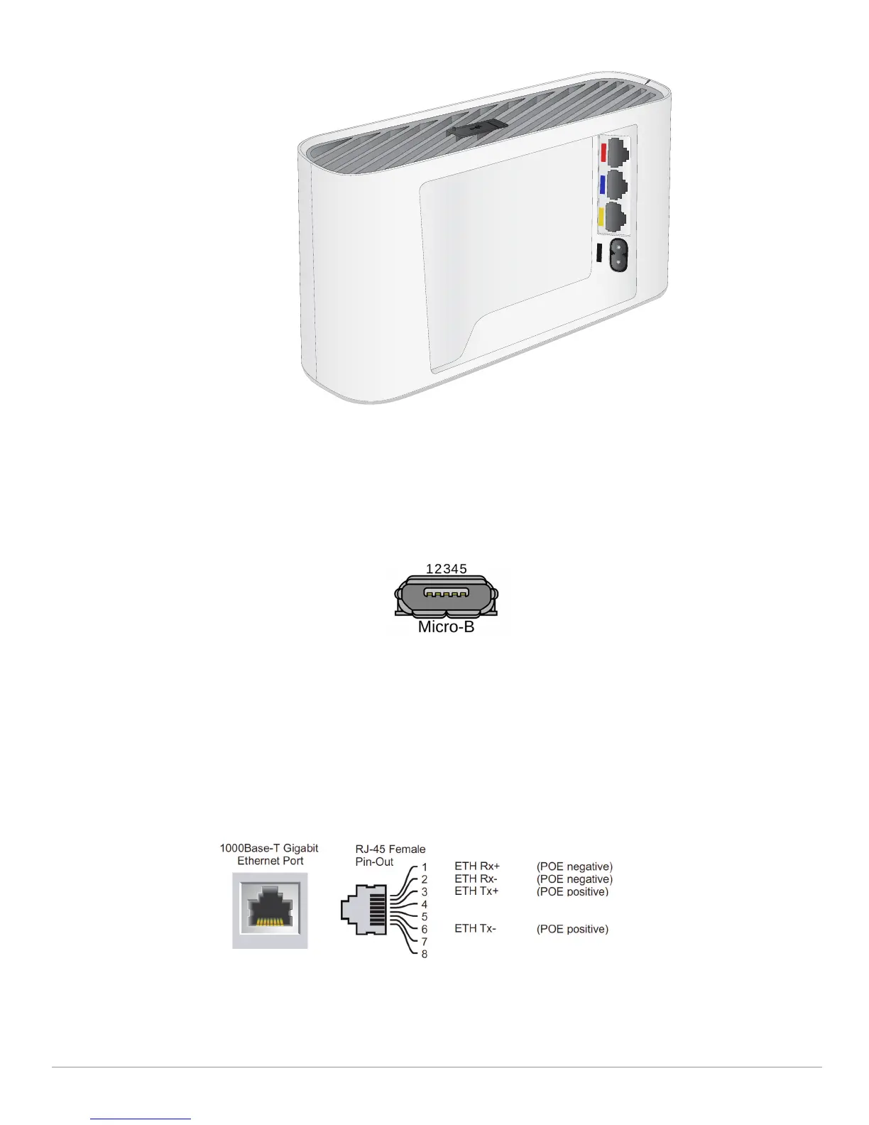
Figure 2 Aruba 203R Series access point (rear view)
Console Port
The 5-pin Micro-B connector located on the bottom of this device. Use an AP-CBL-SERU cable for direct
management of this device when connected to a laptop or serial console. For pin-out details, refer to Figure 3.
Figure 3 Micro-B Port Pin-out
Ethernet Ports
The Aruba 203R Series access point is equipped with three active Ethernet ports (E0-E2), shown in Figure 2.
The E0 port is a 100/1000 Base-T, auto-sensing MDI/MDX, which supports uplink connectivity when linked by an
Ethernet cable.
The E1-E2 ports are 100/1000 Base-T auto-sensing MDI/MDX, which support downlink connectivity. These ports
may be used to provide secure network connectivity and also allows for manual configuration the device when
linked by an Ethernet cable. Refer to Figure 4 for a detailed port pin-out.
The Aruba 203RP access point supports 802.3af PoE-out from the E2 port. This device is capable of supplying up
to 15.4W to a powered device.
Figure 4 Gigabit Ethernet Port Pin-Out
1: NC
2: RX
3: TX
4: GND
5: GND
 Loading...