Aruba 503H Hospitality Access Points | Installation Guide 3
LEDs
The hidden LED displays located on the front panel of the access point indicate the following functions:
System Status
The System Status LED indicates the operating condition of the access point, See Table 1.
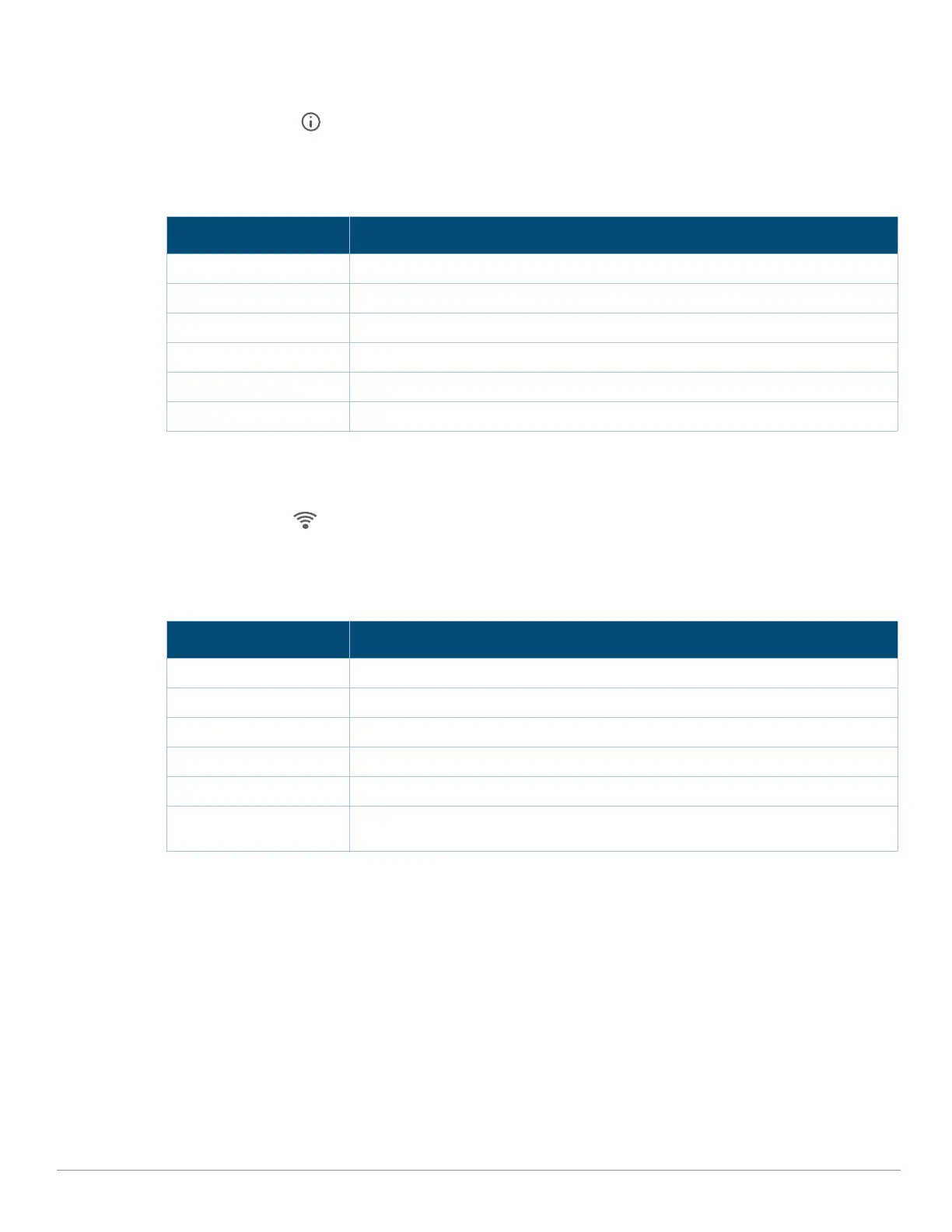
Table 1 System Status LEDs
1 Blinking: one second on/one second off, 2 second cycle.
2 Flashing Pattern 1: mostly on, briefly off, 2 second cycle.
3 Flashing Pattern 2: mostly off, briefly on, 2 second cycle.
Radio Status
The Radio Status LED indicates the operating mode of the access point’s radios. See Table 2.
Table 2 Radio Status LEDs
1 Alternating: one second each color, 2 second cycle.
LED Display Settings
The LEDs have three operating modes that can be selected in the system management software:
Default mode: Refer to Table 1 and Table 2
Off mode: LEDs are off
Blink mode: LEDs blink green
Force the LEDs into off mode and back to software defined mode by pressing the reset button for a short
duration. Warning: pressing the reset button for longer than 10 seconds may cause the AP to reset and return to
factory default state.
Color/State Meaning
Off Device powered off
Green- blinking
1
Device booting, not ready
Green- solid Device ready, fully functional, no network restrictions
Green- flashing pattern 1
2
Device ready, fully functional, uplink negotiated in sub-optimal speed (<1Gbps)
Green- flashing pattern 2
3
Deep sleep mode
Red System error condition - Immediate attention required
Color/State Meaning
Off AP powered off, or both radios disabled
Green- solid Both radios enabled in access mode
Green- blinking One radio enabled in access mode, other disabled
Amber- solid Both radios enabled in monitor mode
Amber- blinking One radio enabled in monitor mode, other disabled
Green/Amber-
alternating
1
Green: one radio in access mode
Amber: one radio in monitor mode