AP-105 Wireless Access Point
Installation Guide
About the Aruba AP-105 Access Points
The Aruba AP-105 wireless access point supports the IEEE 802.11n standard for
high-performance WLAN. This access point uses MIMO (Multiple-in, Multiple-
out) technology and other high-throughput mode techniques to deliver high-
performance, 802.11n 2.4 GHz and 5 GHz functionality while simultaneously
supporting existing 802.11a/b/g wireless services. The AP-105 access point works
only in conjunction with an Aruba Controller.
The Aruba AP-105 access point provides the following capabilities:
z Wireless transceiver
z Protocol-independent networking functionality
z IEEE 802.11a/b/g/n operation as a wireless access point
z IEEE 802.11a/b/g/n operation as a wireless air monitor
z Compatibility with IEEE 802.3af PoE
z Central management configuration and upgrades through an Aruba
Controller
Package Contents
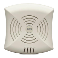
z AP-105 access point (1 unit or a pack of 10)
z Installation guide (this document)
Figure 1 AP-105
AP-105 Hardware Overview
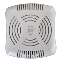
Figure 2 AP-105 Front
LEDs
The AP-105 is equipped with four LEDs that indicate the status of the various
components of the AP.
z PWR: Indicates whether or not the AP-105 is powered-on
z ENET: Indicates the status of the AP-105’s Ethernet port
z 11A/N: Indicates the status of the 802.11a/n radio
z 11B/G/N: Indicates the status of the 802.11b/g/n radio
For information about the AP-105’s LED behavior, see Table 1 on page 2.
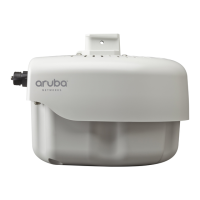
Figure 3 AP-105 Rear
Console Port
Use the console port to connect to a terminal for direct local management.
Ethernet Port
AP-105 is equipped with a single 10/100/1000Base-T (RJ-45) auto-sensing, MDI/
MDX wired-network connectivity port. This port supports IEEE 802.3af Power
over Ethernet (PoE) compliance, accepting 48VDC as a standard defined
Powered Device (PD) from a Power Sourcing Equipment (PSE) such as a PoE
midspan injector, or network infrastructure that supports PoE.
DC Power Socket
If PoE is not available, an optional Aruba AP AC-DC adapter kit (sold separately)
can be used to power the AP-105.
Before You Begin
Pre-Installation Network Requirements
After WLAN planning is complete and the appropriate products and their
placement have been determined, the Aruba controller(s) must be installed and
initial setup performed before the Aruba APs are deployed.
For initial setup of the controller, refer to the ArubaOS Quick Start Guide for
the software version installed on your controller.
AP Pre-Installation Checklist
Before installing your AP-105 access point, be sure that you have the following:
z CAT5 UTP cable of required length
z One of the following power sources:
IEEE 802.3af-compliant Power over Ethernet (PoE) source
Supports full functionality for AP-105
The POE source can be any power source equipment (PSE) controller or
midspan PSE device
Aruba AP AC-DC adapter kit (sold separately)
z Aruba Controller provisioned on the network:
Layer 2/3 network connectivity to your access point
One of the following network services:
z Aruba Discovery Protocol (ADP)
z DNS server with an “A” record
z DHCP Server with vendor-specific options
Summary of the Setup Process
Successful setup of an AP-105 access point consists of five tasks, which must be
performed in this order:
1. Verify pre-installation connectivity.
2. Identify the specific installation location for each AP.
3. Install each AP.
4. Verify post-installation connectivity.
5. Configure each AP.
Verifying Pre-Installation Connectivity
Before you install APs in a network environment, make sure that the APs are
able to locate and connect to the controller after power on.
Specifically, you must verify the following conditions:
z When connected to the network, each AP is assigned a valid IP address
z APs are able to locate the controller
Refer to the ArubaOS Quick Start Guide for instructions on locating and
connecting to the controller.
Identifying Specific Installation Locations
You can mount the AP-105 access point on a wall or on the ceiling. Use the AP
placement map generated by Aruba’s RF Plan software application to determine
the proper installation location(s). Each location should be as close as possible
to the center of the intended coverage area and should be free from obstructions
or obvious sources of interference. These RF absorbers/reflectors/interference
sources will impact RF propagation and should have been accounted for during
the planning phase and adjusted for in RF plan.
Identifying Known RF Absorbers/Reflectors/Interference
Sources
Identifying known RF absorbers, reflectors, and interference sources while in
the field during the installation phase is critical. Make sure that these sources are
taken into consideration when you attach an AP to its fixed location.
RF absorbers include:
z Cement/concrete—Old concrete has high levels of water dissipation, which
dries out the concrete, allowing for potential RF propagation. New concrete
has high levels of water concentration within the concrete, blocking RF
signals.
z Natural Items—Fish tanks, water fountains, ponds, and trees
z Brick
RF reflectors include:
z Metal Objects—Metal pans between floors, rebar, fire doors, air conditioning/
heating ducts, mesh windows, blinds, chain link fences (depending on
aperture size), refrigerators, racks, shelves, and filing cabinets
z Do not place an AP between two air conditioning/heating ducts. Make sure
that APs are placed below ducts to avoid RF disturbances.
RF interference sources include:
z Microwave ovens and other 2.4 or 5 GHz objects (such as cordless phones)
z Cordless headset such as those used in call centers or lunch rooms
Installing the AP
Using the Integrated Wall-Mounting Slots
The keyhole-shaped slots on the back of the AP can be used to attach the device
upright to an indoor wall or shelf. When you choose the mounting location, allow
additional space at the right of the unit for cables.
1. Since the ports are on the back of the device, make sure that you mount the
AP is such a way that there is a clear path to the Ethernet port, such as a pre-
drilled hole in the mounting surface.
2. At the mounting location, install two screw on the wall or shelf, 1 7/8 inches
(4.7 cm) apart. If you are attaching the device to drywall, Aruba recommends
using appropriate wall anchors (not included).
3. Align the mounting slots on the rear of the AP over the screws and slide the
unit into place (see Figure 4).
Figure 4 Installing the AP-105 Access Point on a Wall
Using the Integrated Ceiling Tile Rail Slots
The snap-in tile rail slots on the rear of the AP can be used to securely attach the
device directly to a 15/16" wide, standard ceiling tile rail.
1. Pull the necessary cables through a prepared hole in the ceiling tile near
where the AP will be placed.
2. If necessary, connect the console cable to the console port on the back of the
AP.
Hold the AP next to the ceiling tile rail with the ceiling tile rail mounting slots at
approximately a 30-degree angle to the ceiling tile rail (see Figure 5). Make sure
that any cable slack is above the ceiling tile.
Figure 5 Orienting the Ceiling Tile Rail Mounting Slots
3. Pushing toward the ceiling tile, rotate the AP clockwise until the device
clicks into place on the ceiling tile rail.