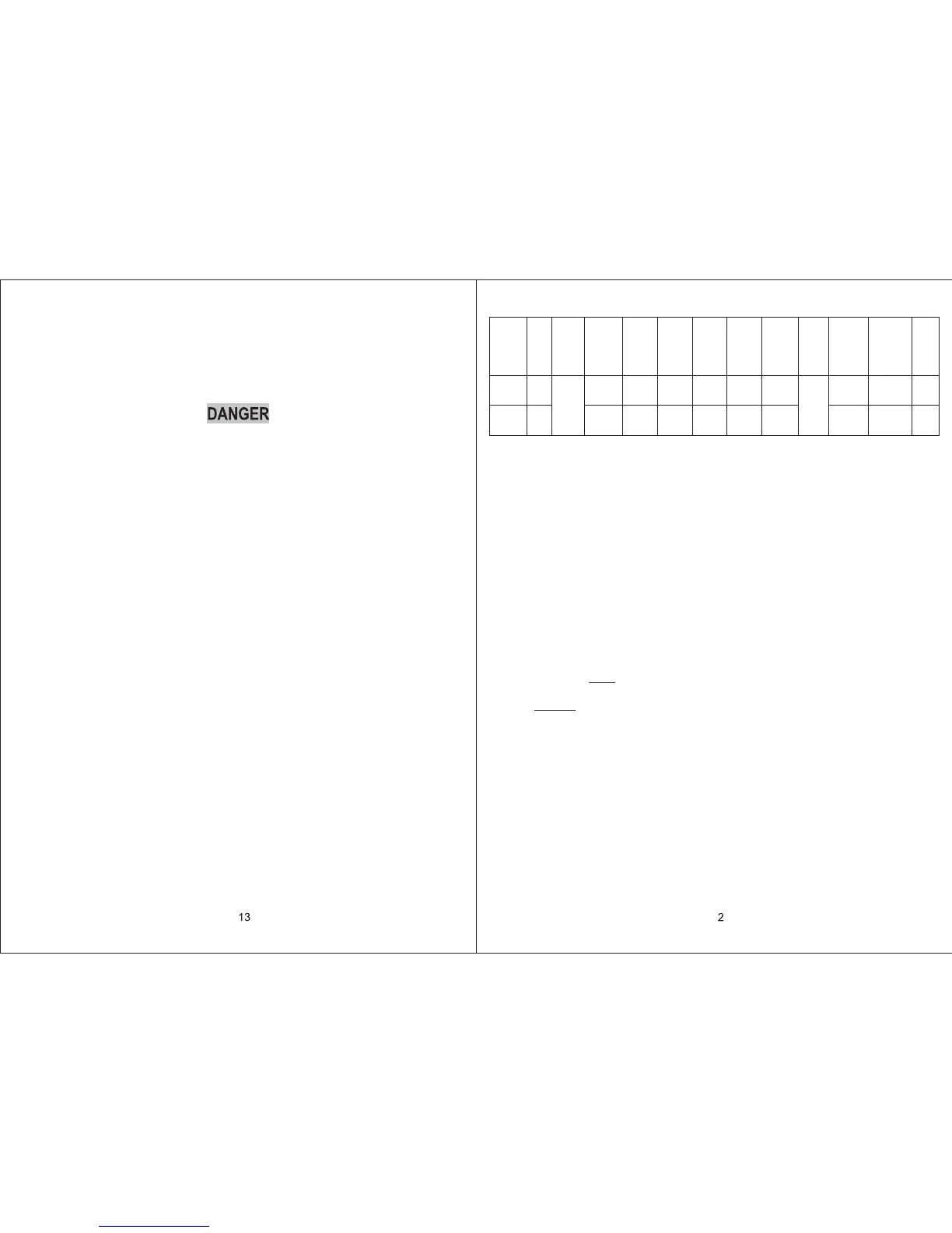
Model
ACM135
ACM150
15000
13500
Rated
BTU
Output
Electrical
Rating
115VAC
60Hz
1PH
Compressor
Rated
Amperage
Fan
Amperage
9.9
12.4
50.5
61
2.6
2.6 5.8
5.8 500
500 16.9
16.9
12AWG
copper
up to
24'
20 Amp
20 Amp
31x24.9x12.9
31x24.9x12.9
68
68
Locked
Rotor
Amperage
Locked
Fan Rotor
Amperage
Air Flow
(High
Speed)
(cfm)
Refrigerant
(R410a)
(oz)
Weight
(Ibs)
Min. wire
size
AC circuit
protection
(User
supplied)
Unit
dimensions
(in)
Notes:
1. Consult the National Electric Code for proper sizing for wire lengths over 24 ft.
2. When sizing the generator, the total power usage of your recreational vehicle
must be considered. Keep in mind generators lose power at high altitudes and
from lack of maintenance.
3. CIRCUIT PROTECTION: Time Delay Fuse or HACR Circuit Breakers Required.
INSTALLATION INSTRUCTIONS
1. PRECAUTIONS
2. CHOOSING A LOCATION FOR THE AIR CONDITIONER / HEAT PUMP
A. Read installation and operating instructions carefully before attempting to start
your air conditioner / heat pump installation.
B. The manufacturer will not be liable for any damages or injury incurred due to failure
to follow these instructions.
C. Installation must comply with the National Electrical Code and any State or Local
Codes or regulations.
D. DO NOT add any devices or accessories to this air conditioner / heat pump except
those specifically authorized by manufacturer.
E. This equipment must be serviced by qualified personnel and some states require
licensed personnel.
This product is designed for use as a RV roof top air conditioner / heat pump. The use
of this product in other applications will void the manufactures warranty.
A. NORMAL LOCATIONS:
The unit is designed to fit over an existing roof vent opening. When the vent is
removed, it normally creates a 14-1/4" x14-1/4"±1/8" opening.
B. OTHER LOCATIONS:
When a roof vent is not available or another location is desired, the following is
recommended:
CONNECTING 115VAC WIRING
1. WARNING - SHOCK HAZARD: To prevent the possibility of severe personal injury or
equipment damage due to electrical shock, always be sure the electrical power is
disconnected or off before beginning installatiom.
2. Route the 115VAC supply wiring previously routed into the frame of the roof opening,
through the strain relief of the electrical box and into the high voltage wiring area.
TO PREVENT THE POSSIBILITY OF SHOCK INJURY FROM APPLIANCE
OPERATION: THE WHITE WIRE MUST BE CONNECTED TO NEUTRAL IN THE
SERVICE BOX ENTRANCE AND THE GREEN GROUND WIRE MUST BE
CONNECTED TO A GROUNDING SCREW.
ATTACH CEILING GRILL
1. Position the grill next to the interior frame and attach it with the provided screws.
2. Install the filter on the air intake grill section.
3. Snap the intake grill section onto the main grille.
4. Install the screw covers.
MAINTENANCE
1. AIR FILTER:
Remove the return air filter (after every 30 days of use) located above the removable
air intake grill. Wash the filter with soap and warm water, let dry and then reinstall.
Note: Never run the air conditioner / heat pump without putting the air filter back in
place. This may plug the indoor coil with dirt and may substantially affect the
performance of the unit.
2. Air Return Grill:
Clean panel and control panel with a soft cloth dampened with a mild detergent. Never
use furniture polish or harsh chemicals.
3. FAN MOTOR:
Factory lubricated and requires no service.
4. FROST FORMATION ON COOLING COIL:
Under certain conditions, frost may form on the indoor coil. If this should occur, inspect
the filter and clean if dirty. Make sure air louvers are not obstructed. Air conditioners /
heat pumps have a greater tendency to frost when the outside temperature is relatively
low. This may be prevented by adjusting the thermostat control to a warmer setting.
SERVICE
If the unit does not operate:
1. If RV is connected to a generator, check to be sure generator is running and producing
the proper power.
2. If RV is connected to shore power, check to be sure supply breaker is sized properly to
run air conditioner / heat pump load and it is plugged into power supply.
3. Check your fuse or circuit breaker to see if it is off.
4. After the above checks, call your local service center for further help. This unit must be
serviced by qualified service personnel only.
ACM135SP
ACM150SP
 Loading...