4.The ACRG has a 6pin, two 3 pin & two 2 pin connectors extending from the front of
the relay kit. These connectors mate with the air conditioner / heat pump. When
making this connection, verify that the plugs are properly aligned and have snapped
together securely.
5.Provided with the ACRG,is a divider plate which is used to separate the warm return
air from the cold supply air. If the roof thickness is greater than 2.5", you MUST use the
additional divider provided.
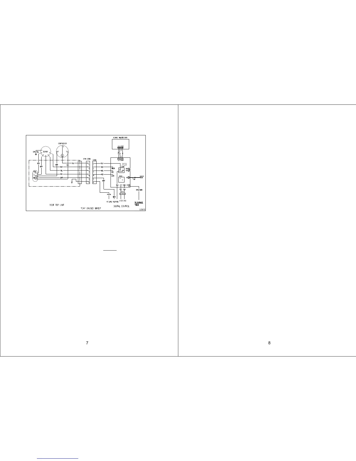
FIGURE 5B WIRING DIAGRAM FOR AIR CONDITIONER ONLY
SUPPLY DUCTING AND REGISTERS
A. Ducting
1. The field fabricated supply ducting must attach to both sides of the ACRG . A
minimum of two ducts are required, with one duct attached to each side of the plenum.
2. Each duct must have a minimum height of 1-1/2". Maximum height cannot exceed 4".
Total free area inside each duct must be no less than 10 square inches.
NOTE: To decrease restriction and increase airflow, the ducting should make as few bends
and turns as possible. When corners or turns are required, we recommend that you
add radii to the corners to keep airflow at a airflow and system performance.
3. All field fabricated air supply ducting must be insulated to avoid condensation and
prevent cooling / heating loss.
B. Registers
Air registers should have a minimum discharge area of 48 square inches per system, or 24
square inches per duct run.
Warnings about wiring:
1. U.L. approval requires the power supply to be copper conductors with minimum #12AWG.
2. To prevent voltage drops greater than 10% during starting loads, adhere to the following
guideline: For lengths greater than 50 feet, use #10 AWG.
TEMPLATE MOUNTING
Frame Mounting
1. Place the air conditioner / heat pump over the roof opening.
2. Install freeze sensor(see below Fig.6). Some air conditioners / heat pumps may contain
a preinstalled, plastic, retaining clip for the freeze sensor. If the clip is present in the
evaporator coil, please use this clip and discard the clip that came with the freeze sensor.
Insert the freeze sensor into the plastic clip and ensure the freeze sensor is secured
properly in the clip. Connect the freeze sensor harness to the relay box mating harness.
3. Position the mount frame into the ceiling opening. See Figure 7.
4. Using the four bolts provided, hold up the mount template to the ceiling. The four mounting
bolts are to be inserted up through the bottom of the mount template and into the bottom
of the air conditioner / heat pump. Tighten all 4 boles equally to compress gasket 33-35
inch pounds. When moving the air conditioner / heat pump be sure not to damage the
gasket by sliding it across the roof. If the gasket is damaged and needs replaced, please
contact ASA Electronics and purchase an authorized Advent gasket for replacement.
Using other gasket material is not recommended and could result in warranty denial.
5. Install divider with foam seal against base pan of upper unit. On thinner roofs, the divider
may be too high, so break away additional portion. Remove paper cover on fixed divider,
insert loose divider against base pan and stick to fixed divider.
6. Cut the insulation to the height of the divider, center insulation on divider before removing
paper backing and apply to divider. Excess insulation will help ensure the seal at the end
of the divider/frame.
7. Connect 115VAC and 12VDC wires, Freeze Sensor Thermistor, Heat Pump specific
(Outdoor Coil Thermistor, Outdoor Ambient Thermistor), and thermostat cable according
to the wiring diagram. Install the cover over the electrical box using the small screw
provided as shown in Figure 7.
8. Seal all seams between output airside and return airside with insulation and foil tape.
RED/ WHT
 Loading...