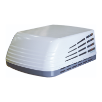
C. POST LOCATION SELECTION:
1. Check for obstructions in the area where air conditioner / heat pump will be
installed. A minimum clearance of 18" is required for the rear section of the air
conditioner / heat pump to any other roof mounted object.
2. The roof must be capable of supporting 100 Ibs while the RV is in motion. Normally,
a 200 Ib. static load design will meet this requirement.
3. ROOF PREPARATION
A. EXISTING ROOF VENT REMOVAL:
1.Unscrew and remove the roof vent.
2. Remove all caulking compound around opening.
3. Seal all screw holes and seams where the roof gasket will be located. Use a good
grade of all weather sealant.
B. NEW OPENING:
1.A 14-1/4" x 14-1/4"+1/8" opening must be cut through the roof and ceiling of the RV.
It is recommended this opening be located between roof framework.
2. Mark a 14-1/4" x 14-1/4" square on the roof and carefully cut the opening.
3. Using the roof opening as a guide, cut the matching hole in the ceiling. See FIG.3.
There may be electrical wiring between the roof and
the ceiling. Disconnect 120 volt AC power cord and the
positive (+) 12 volt DC terminal at the supply battery.
Failure to follow this instruction may create a shock
hazard causing death or severe personal injury.
WARNING
!
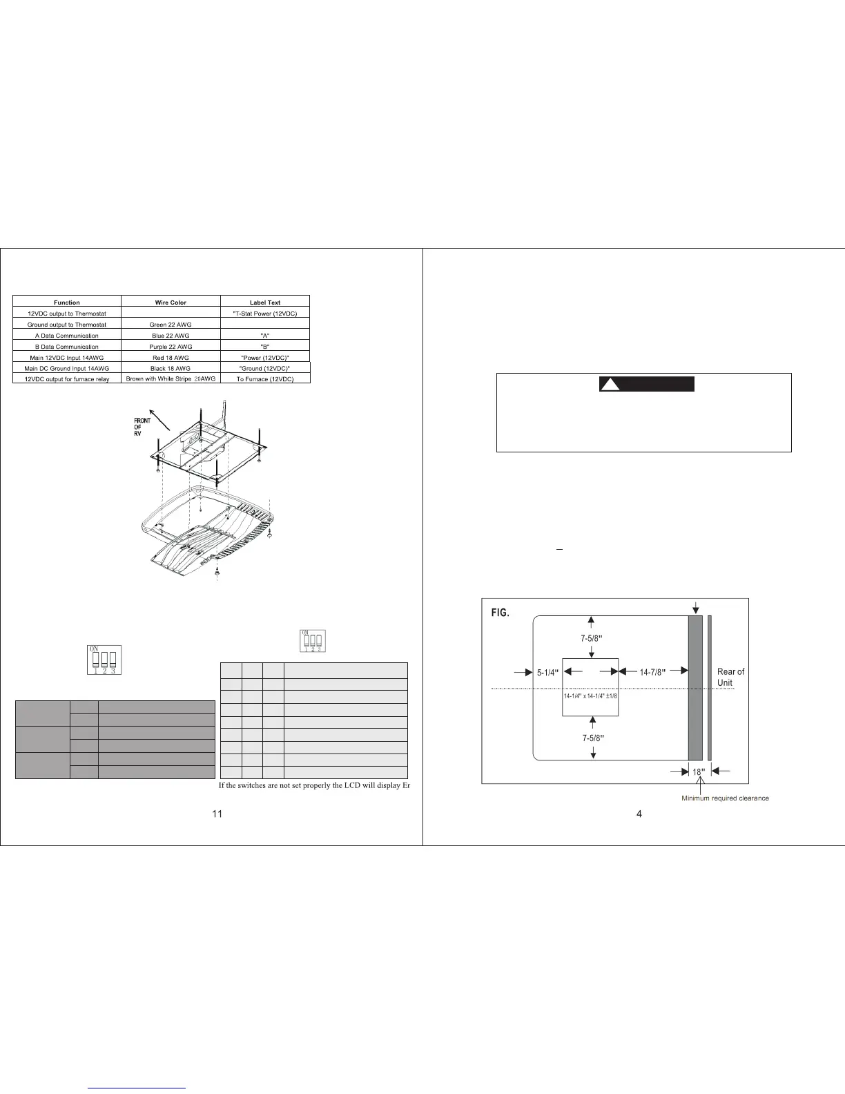
MAIN RELAY KIT WIRING
THERMOSTAT DIP SWITCH SETTINGS:
Dip switch
As shown ALL OFF
Default Setting is 1 OFF, 2 OFF, 3 ON
Dip Switch1
Dip Switch2
Dip Switch3
On
Off
On
Off
On
Off
Heat Strip function disable
Heat Strip function enable
Heat Pump function disable
Heat Pump function enable
Furnace function disable
Furnace function enable
ON
OFF OFF OFF
OFF OFF
OFF OFF
OFF OFF
OFF
ON
ON
ONON
ONONOFF
OFF ON
ON
ON
ON ON
SW1 SW2 SW3
Mode Cycle
FAN - COOL
FAN - COOL - HEAT STRIP
FAN - COOL - HEAT PUMP
FAN - COOL - FURNACE
Configuration not possible
Configuration not possible
FAN - COOL - HEAT PUMP - FURNACE
FAN - COOL - HEAT STRIP - FURNACE
Dip swit ch
FIG.7
Red with White Stripe 22 AWG
COM
.3