C. OPENING PREPARATION:
1. If the opening exceeds 14-3/8" x 14-3/8", it will be necessary to install spacers.
2. If the opening is less than 14-1/8" x 14-1/8", it must be enlarged.
3. Route a 12/3 Rmoex type supply line from the circuit breaker box to the Front of
the roof opening.
a. The power supply must be on a separate 20 amp Time Delay Fuse or HACR
Circuit Breaker.
b. Wiring must comply with all National, State and Local wiring codes.
c. Make sure at least 15" of wire extend into the roof opening to ensure easy
connections.
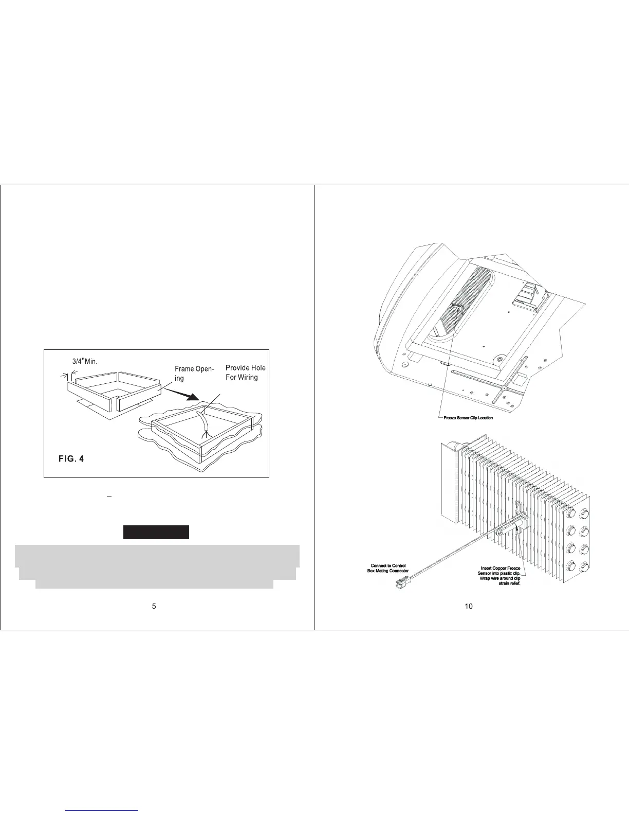
4. The opening must be framed to provide adequate support and prevent air from
being drawn from the roof cavity. Lumber 3/4" thick or more and long enough to
bridge the opening must be used. Remember to provide an entrance hole in the
front of the opening for 110v, 12v, and thermostat wires. See FIG.4.
5. The 14-1/4" x14-1/4"(+1/8) roof opening is part of the return air duct and must be
finished in accordance with NFPA standard 501C, Standard for Recreational
Vehicles, Section 2-7.
CAUTION
It is the responsibility of the installer of this system to ensure structural
integrity of the RV roof. Never create a low spot on the roof where water
will collect. Water standing around the air conditioner/heat pump may
leak into the interior causing damage to the product and RV
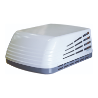
ALTERNATIVE FREEZE SENSOR INSTALLATION
Check Upper Unit to see if freeze sensor clip is preinstalled in evaporator fins. If so,
insert the copper sensor from the Ducted Ceiling kit into the clip as show below.