_____________________________________________________________________
ATLANTIC SATELLITE CORPORATION
MODEL ASC300LW
BEACON RECEIVER
6
4.0
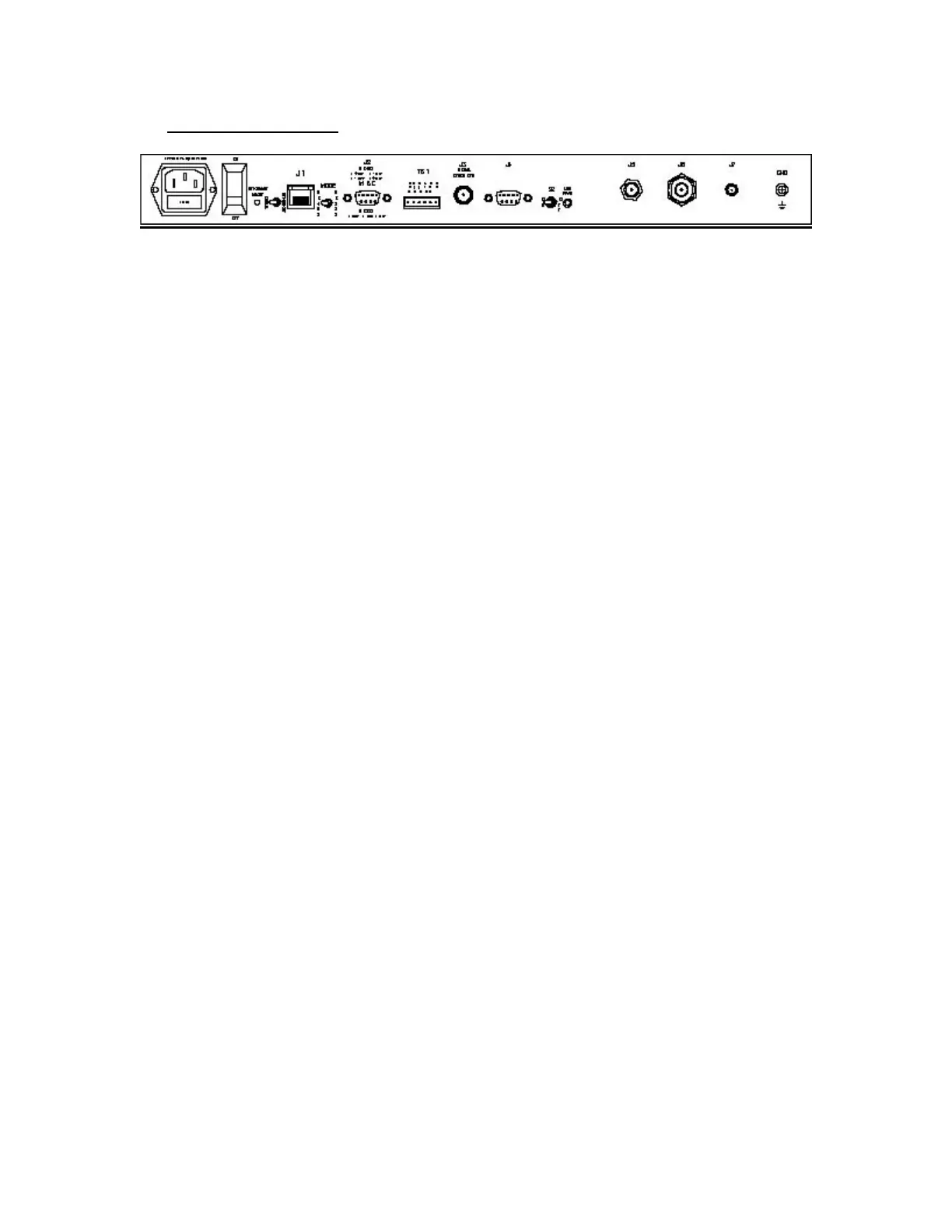
Rear Panel Facilities:
J1: RJ-45 (ETHERNET OPTIONAL) Not a standard install.
MODE: Selection switch for RS-232 or RS-485 external
communication.
J2: M&C
The monitor and control input is a female DB-9
connector. The pins for the appropriate interface are:
RS-232: Pin 2 – Transmit
Pin 3 – Receive
Pin 5 – Ground
RS-485 (optional):
Pin 6 – Transmit +
Pin 7 – Transmit -
Pin 8 – Receive –
Pin 9 – Receive +
Pin 5 – Ground
TB1:
Term. 1: Alarm relay common contact
Term. 2: Alarm relay normally open contact
Term. 3: Alarm relay normally closed contact
Term. 4: AFC voltage. When the unit is locked to the carrier the
voltage will be approx.2.05 VDC.
Term. 5: Signal Ground
Term. 6: Signal strength output voltage (SS)
J3: SIGNAL STRENGTH (BNC) The signal strength voltage ranges
from 0 to + 10 VDC as a function of input signal level. The voltage slope
is 0.5 V/dB over a 20 dB input signal change.
S2: LNB Voltage, +18 VDC, 500 ma, max., Switchable In/Out on input
connector center conductor.
AC RECEPTACLE: 90-264 VAC, 47-63 Hz Input, auto-sensing. Spare
fuse compartment within receptacle.\