8.2.2 PLC Outputs
O-1 disengage motor control
O-2 relay platform motor
O-3 safety bar motor top
O-4 safety bar motor down
O-5 reverse polarity relay K1
O-6 moving magnet
O-7 beeper (emergency call)
O-8 free
O-9 flasher (optical and acoustical warning signal)
O-A free
8.3 Operation time counter/Power blackout counter/Battery voltage
Operation time counter:
The operation time counter only counts whole driving
hours. Every movement on the lift (drive UP / DOWN,
fold platform ...) is part of the driving time.
Power blackout counter:
Records how often the PLC was switched off (due to
low batteries or power failure)
Battery voltage:
If the lift is parked at the station the charging voltage is shown.
When the lift is moving or standing between the stations the battery voltage is displayed.
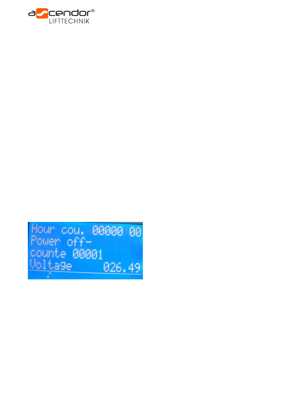
The above shown PLC display shows following values:
Hour cou. = 0 Hours
Power off-counter = 1
Voltage = 26,49 V