ASCO Valves
®
E267747 - 10/2016 All Rights Reserved I&M V_9810_R2
©
ASCO Valve, Inc.
50 Hanover Road, Florham Park, New Jersey 07932 www.ascovalve.com Page 1 of 4
I&M V_9810_R2
Installation & Maintenance Instructions
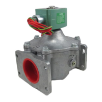
2-WAY INTERNAL PILOT-OPERATED SOLENOID VALVES
NORMALLY CLOSED OPERATION
GENERAL SERVICE - 3/8",1/2" OR 3/4" NPT
3. Remove bonnet screws from valve body.
4. Lift valve bonnet slightly and rotate to desired position. Do not
rotate the diaphragm assembly with the valve bonnet.
5. Replace bonnet screws and torque in a crisscross manner to 95 ± 10
in-lbs [10,7 ± 1,1 Nm].
6. Position and tighten solenoid in place,see separate instructions.
WARNING: To prevent the possibility of death,
serious injury or property damage, check valve for
proper operation before returning to service.
AVERTISSEMENT: Afi n d’éviter le risque de mort,
de blessure ou de dommage matériel, vérifi er le bon
fonctionnement de l’électrovanne avant de la remettre
en service.
7. Test operate valve electrically and manually. Be sure valve can be
test operated without affecting other equipment.
8. Restore line pressure and electrical power supply to valve.
INSTALLATION
Check nameplate for correct catalog number, pressure, voltage, frequency,
and service. Never apply incompatible fl uids or exceed pressure rating
of the valve. Installation and valve maintenance to be performed by
qualifi ed personnel.
Future Service Considerations
Provision should be made for performing seat leakage, external leakage,
and operational tests on the valve with a nonhazardous, noncombustible
fl uid after disassembly and reassembly.
Temperature Limitations
For maximum valve ambient and fl uid temperatures, refer to chart
below or as limited by solenoid approvals. See solenoid installation and
maintenance instructions. Check catalog number and watt rating on
nameplate.
SERIES
8210G
[42]
1.66
.28 dia.
2 mounting holes
[Ø7.1]
NOTICE: See separate solenoid installation and maintenance
instructions for information on: Wiring, Solenoid Temperature,
Cause of Improper Operation, Coil or Solenoid Replacement.
DESCRIPTION
Series 8210 valves are 2-way normally closed internal pilot-operated
solenoid valves designed for general service. Valves are made of rugged
forged brass. Series 8210 valves are provided with a general purpose
solenoid enclosure.
Series EF8210 are the same as Series 8210 except they are provided with
an explosionproof/watertight solenoid enclosure.
Notice: Standard brass valves are not certifi ed as lead-free under the
Safe Drinking Water Act SDWA 1417 and are not intended for use
on drinking water systems. They are intended for control of water
in industrial applications. Consult ASCO for valves rated for use in
potable water applications.
Notice: Constructions with an “LF” suffi x meet the lead free-brass
requirement of SDWA 1417 having 0.25% or less lead (Pb) in brass.
Due to the variety of operating conditions and applications of these
products, the user, through analysis and testing, is solely responsible
for making the fi nal selection of the products and assuring that all
performance, safety, and warning requirements of the applications
are met.
OPERATION
Normally Closed: Valve is closed when solenoid is de-energized; open
when energized.
IMPORTANT: Minimum operating pressure differential required is
5 psi.
Manual Operator (optional feature)
Manual operator allows manual operation when desired or during an
electrical power outage. To engage manual operator (open the valve),
push in knurled cap and rotate stem clockwise 180°. Valve will now
be in the same position as when the solenoid is energized. To disengage
manual operator (close the valve), turn stem counterclockwise 180°.
Push in and rotate
180° clockwise to operate
CAUTION: For valve to operate electrically, manual
operator stem must be fully rotated counterclockwise.
ATTENTION: Afi n que la vanne fonctionne électriquement,
la commande manuelle doit être complètement tournée dans
le sens inverse des aiguilles d’une montre.
Relocation of Manual Operator
Manual operator may be relocated at 90° increments by rotating the
valve bonnet as follows:
WARNING: To prevent the possibility of death,
serious injury or property damage, turn off electrical
power, depressurize valve, and vent fl uid to a safe
area before relocating manual operator.
AVERTISSEMENT:
Pour éviter tout risque de décès,
de blessure grave ou de dégâts matériels, avant
de remettre en place l’opérateur manuel : couper
l’alimentation électrique, dépressuriser la vanne et
purger le fl uide dans une zone sûre.
1. See separate solenoid installation and maintenance instruction’s and
follow instructions to loosen solenoid to allow rotation of enclosure.
2. Be sure manual operator stem is fully rotated counterclockwise.
Positioning
This valve is designed to perform properly when mounted in any position.
However, for optimum life and performance, the solenoid should be
mounted vertically and upright to reduce the possibility of foreign matter
accumulating in the solenoid base sub-assembly area.
Mounting
For mounting bracket (optional feature) dimensions, refer to Figure1.
Figure 1. Mounting bracket dimensions
Piping
Connect piping to valve according to markings on valve body. Apply pipe
compound sparingly to male pipe threads only. If applied to valve threads,
the compound may enter the valve and cause operational diffi culty. Avoid
pipe strain by properly supporting and aligning piping. When tightening
the pipe, do not use valve or solenoid as a lever. Locate wrenches applied
to valve body or piping as close as possible to connection point.
Wattage
Catalog Number
Coil Prefi x
Coil
Class
Max.
Ambient
Temp.°F
Max.
Fluid
Temp.°F
6.1, 10.1 NONE F 125°F 180°F
6.1, 10.1 HT H 140°F 180°F
11.6 NONE OR HT F OR H 104°F 150°F