Page 1 of 3
50 Hanover Road, Florham Park, New Jersey 07932 www.ascovalve.com
All Rights Reserved.E188413
Installation & Maintenance Instructions
SERIES
8320
BRASS OR STAINLESS STEEL CONSTRUCTION
I&M No.V7569
3-WAY NORMALLY CLOSED DIRECT MOUNTED SOLENOID VALVES
FOR NAMUR ACTUATORS Ċ 1/4I NPT Ċ AIR OR INERT GAS SERVICE
NOTICE: See separate solenoid installation and maintenance
instructions for information on: Wiring, Solenoid Temperature,
Causes of Improper Operation and Coil or Solenoid Replacement.
DESCRIPTION
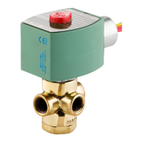
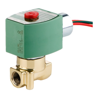
Series 8320 valves are 3-way normally closed direct mounted
solenoid valves designed for air or inert gas service. Valves are
made of rugged brass or stainless steel. Series 8320 valves are
provided with a general purpose solenoid enclosure. Series
EE8320 is the same as Series 8320 except it is provided with a Class
I, Division 2 explosionproof/watertight solenoid enclosure.
OPERATION
Normally Closed (Pressure at Port 1)
Solenoid De-energized: Flow is from Port 2 to Port 3. Port 1 is
closed.
Solenoid Energized: Flow is from Port 1 to Port 2. Port 3 is closed.
Breather Function: Allows for spring side of a spring return actuator to
vent at all times through valve exhaust port 3. IMPORTANT: Because
of the breather function, the use of a metering / flow control device at
exhaust port 3 (to control actuator speed) is not recommended.
NOTICE: No minimum operating pressure differential required.
SOLENOID
DE-ENERGIZED
SOLENOID
ENERGIZED
FLOW DIAGRAMS
12
3
12
3
Manual Operation
Manual operator (optional feature) allows manual operation when
desired or during an electrical power outage. Depending upon valve
requirements, two types of manual operators are available:
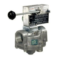
Momentary Push Type (Suffix MO) Manual Operator
To engage push type manual operator, push stem at base of valve body
upward as far as possible. Valve will now be in the same position as
when the solenoid is energized. To disengage manual operator,
release stem. Manual operator will return to original position.
Maintained Screw Type (Suffix MS) Manual Operator
To engage screw type manual operator, turn red knob clockwise until
it hits a stop. Valve will now be in the same position as when solenoid
is energized. Rotate knob fully counterclockwise to disengage.
CAUTION: For valve to operate electrically, manual
operator must be fully disengaged.
INSTALLATION
Check nameplate for correct catalog number, pressure, voltage,
frequency, and service. Never apply incompatible fluids or exceed
pressure rating of the valve. Installation and valve maintenance to be
performed by qualified personnel.
Future Service Considerations
Provision should be made for performing seat leakage, external
leakage, and operational tests on the valve with a nonhazardous,
noncombustible fluid after disassembly and reassembly.
Temperature Limitations
See separate solenoid Installation and Maintenance Instructions for
maximum ambient temperature Maximum fluid temperature is
180_F (82_C)
Positioning
Valve may be mounted in any position.
Mounting Solenoid Valve to NAMUR Actuator
Valves are supplied with a hardware kit containing two port gaskets
and three sets of mounting screws; sizes: M5, .190-24 UNC-2A and
.190-32 UNF-2A. Align port 2 and 3 port gaskets and solenoid
valve on actuator. Then install two hex head screws in offset center
holes on either side. Hand thread screws a few turns into actuator.
Then tighten screws evenly using a 5/16
I or 8 mm wrench.
Figure 1. Mounting Dimensions
1.26
[32]
.95
[24]
2 mounting holes
locating hole
port gaskets (2)
3
2
Piping
Apply pipe compound sparingly to male pipe threads only. If applied
to valve threads the compound may enter the valve and cause
operational difficulty. Avoid pipe strain by properly supporting and
aligning piping. When tightening the pipe, do not use valve or
solenoid as a lever. Locate wrenches applied to valve body or piping
as close as possible to connection point.
NOTE: The exhaust and/or pressure lines may be restricted to
control actuator speed.
CAUTION: To protect the solenoid valve, install a strainer
or filter, suitable for the service involved, in the inlet side as
close to the valve as possible. Clean periodically depending
on service conditions. See ASCO Series 8600, 8601, and 8602
for strainers.