EasyManua.ls Logo

ASCO Valves 8262 Series - User Manual

ASCO Valves 8262 Series
4 pages
Print Icon
To Next Page IconTo Next Page
Loading...
Page 1 of 4
50-60 Hanover Road, Florham Park, New Jersey 07932
ASCO Valves
MCMXCIII. All Rights Reserved
Printed in U.S.A.
Installation & Maintenance Instructions
SERIES
Form No.V5256R8
2-WAY DIRECT-ACTING SOLENOID VALVES
BRASS OR STAINLESS STEEL CONSTRUCTION - 1/8, 1/4, OR 3/8 NPT
8262
8263
NORMALLY OPEN OR NORMALLY CLOSED OPERATION
IMPORTANT: See separate solenoid installation and maintenance
instructions for information on: Wiring, Solenoid Temperature,
Causes of Improper Operation, and Coil or Solenoid Replacement.
DESCRIPTION
Series 8262 and 8263 valves are 2-way direct-acting general service
solenoid valves. Valves bodies are of rugged brass or stainless steel.
Series 8262 or 8263 valves may be provided with a general purpose or
explosionproof solenoid enclosure. Series 8262 and 8263 valves with
suffix P" in the catalog number are designed for dry inert gas and
non-lubricated air service.
OPERATION
Normally Open: Valve is open when solenoid is de-energized; closed
when is energized.
Normally Closed: Valve is closed when solenoid is de-energized;
open when energized.
IMPORTANT: No minimum operating pressure required.
Manual Operation
Manual operator allows manual operation when desired or during an
electrical power outage. Depending upon basic valve construction,
three types of manual operators are available:
Push Type Manual Operator
To engage push type manual operator, push stem at base of valve body
upward as far as possible. Valve will now be in the same position as
when the solenoid is energized. To disengage manual operator, reĆ
lease stem. Manual operator will return to original position.
Screw Type Manual Operator
To engage screw type manual operator, rotate stem at base of the
valve body clockwise until it hits a stop. Valve will now be in the same
position as when the solenoid is energized. To disengage, rotate stem
counterclockwise until it hits a stop.
CAUTION: For valve to operate electrically, manual operator
stem must be fully rotated counterclockwise.
Stem/Lever Type Manual Operator
To engage manual operator, turn stem/lever clockwise until it hits a
stop. Valve will now be in the same position as when the solenoid is
energized. To disengage manual operator, turn stem/lever counterĆ
clockwise until it hits a stop.
CAUTION: For valve to operate electrically, manual operator
stem/lever must be fully rotated counterclockwise.
Flow Metering Devices
Valves with suffix M" in catalog number are provided with a meterĆ
ing device for flow control. Turn stem to right to reduce flow; left to
increase flow.
INSTALLATION
Check nameplate for correct catalog number, pressure, voltage,
frequency, and service. Never apply incompatible fluids or exceed
pressure rating of the valve. Installation and valve maintenance to be
performed by qualified personnel.
Note: Inlet port will either be marked I" or IN". Outlet port will be
marked 2" or OUT".
Future Service Considerations.
Provision should be made for performing seat leakage, external leakĆ
age, and operational tests on the valve with a nonhazardous,noncomĆ
bustible fluid after disassembly and reassembly.
Temperature Limitations
For maximum valve ambient and fluid temperatures, refer to charts
below. Check catalog number, coil prefix, suffix, and watt rating on
nameplate to determine the maximum temperatures.
Wattage
Catalog
Number
Coil
Prefix
Coil
Class
Max.
Ambient
Temp. F
Max.
Fluid
Temp. F
6, 10.5,
12.4
none,ĂDA or
S
A 77 180
6,10.5
12.4
DF, FT
or SF
F 125 180
6,10.5,
12.4
HT H 140 180
9,10.7
none, DP or
SP
F 77 180
9.7
none, FT or
HT
A, F
or H
77 120
11.2
none, FT or
HT
A, F
or H
77 150
16.7
none, DP or
SP
F 77 200
17.1
none, KP
SP or SD
F 125 180
17.1
HB, KB SS
or SV
H 140 180
Catalog Nos.8262B200 and 8262 C200 AC construction only and
Catalog Nos.8262B214 and 8262 D200 AC and DC construction are
limited to 140F fluid temperature.
Valves with Suffix V or W that are designed for AC service and norĆ
mally closed operation are for use with No. 2 and 4 fuel oil service.
These valves have the same maximum temperatures per the above
table except Suffix W valves are limited to a maximum fluid temperaĆ
ture of 140F.
Listed below are valves with Suffix V in the catalog number that are
acceptable for higher temperatures.
Catalog Number
Coil Prefix
Max. Ambient
Temp.F
Max. Fluid
Temp.F
FT8262, HB8262
FT8263, HB8263
8262G, 8263G
125 250*
HT or HB 8262G
HT or HB 8263G
140 250
*The only exception is the 8262G and 8263G series (Class F coil) at 50
Hertz rated 11.1 and 17.1 watts are limited to 210F fluid temperature.
Positioning
This valve is designed to perform properly when mounted in any posiĆ
tion. However, for optimum life and performance, the solenoid
should be mounted vertically and upright to reduce the possibility of
foreign matter accumulating in the solenoid base sub-assembly area.
Question and Answer IconNeed help?

Do you have a question about the ASCO Valves 8262 Series and is the answer not in the manual?

Overview

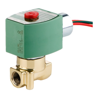
This document describes the installation and maintenance procedures for ASCO Series 8262 and 8263 2-way direct-acting solenoid valves. These valves are designed for general service and are available in brass or stainless steel construction with 1/8", 1/4", or 3/8" NPT connections. They can be configured for either normally open or normally closed operation. Some models, identified by a "P" suffix in the catalog number, are specifically designed for dry inert gas and non-lubricated air service.

Function Description:

The Series 8262 and 8263 valves are 2-way direct-acting solenoid valves. In normally open configurations, the valve is open when the solenoid is de-energized and closes when energized. Conversely, in normally closed configurations, the valve is closed when the solenoid is de-energized and opens when energized. A key feature is that no minimum operating pressure is required for these valves.

Important Technical Specifications:

The valves are available with various wattage ratings and coil prefixes, which determine their maximum ambient and fluid temperature limitations. For instance, a 6, 10.5, or 12.4 Watt valve with no coil prefix (or DA, S) has a Coil Class A, with a maximum ambient temperature of 77°F and a maximum fluid temperature of 180°F. A 6, 10.5, or 12.4 Watt valve with DF, FT, or SF coil prefixes has a Coil Class F, with a maximum ambient temperature of 125°F and a maximum fluid temperature of 180°F. For HT coil prefixes at the same wattage, the Coil Class is H, allowing for a maximum ambient temperature of 140°F and a maximum fluid temperature of 180°F. Higher wattage valves (e.g., 16.7W with DP or SP coil, Class F) can handle fluid temperatures up to 200°F, while 17.1W valves with KP SP or SD coil (Class F) have a maximum ambient temperature of 125°F and a maximum fluid temperature of 180°F. Specific models like 8262B200, 8262C200 (AC only), 8262B214, and 8262D200 (AC and DC) are limited to 140°F fluid temperature. Valves with suffix V or W for AC service and normally closed operation are for No. 2 and 4 fuel oil service, with a maximum fluid temperature of 140°F for suffix W valves. Certain models (FT8262, HB8262, FT8263, HB8263, 8262G, 8263G) can handle up to 250°F fluid temperature with a 125°F ambient temperature (Class F coil). The 8262G and 8263G series (Class F coil) at 50 Hertz rated 11.1 and 17.1 watts are limited to 210°F fluid temperature.

Usage Features:

  • Manual Operation: The valves can be operated manually, which is useful for desired manual control or during electrical power outages. Three types of manual operators are available:
    • Push Type: To engage, push the stem at the base of the valve body upward until it stops. To disengage, release the stem.
    • Screw Type: To engage, rotate the stem clockwise until it stops. To disengage, rotate counterclockwise until it stops.
    • Stem/Lever Type: To engage, turn the stem/lever clockwise until it stops. To disengage, turn counterclockwise until it stops.
    • Caution: For electrical operation, the manual operator stem must be fully rotated counterclockwise.
  • Flow Metering Devices: Valves with an "M" suffix in the catalog number include a metering device for flow control. Turning the stem to the right reduces flow, while turning it to the left increases flow.
  • Positioning: While the valve is designed to perform properly in any position, mounting the solenoid vertically and upright is recommended for optimum life and performance. This orientation helps reduce the possibility of foreign matter accumulating in the solenoid base sub-assembly area. Valves with a "P" suffix must be mounted vertically and upright.
  • Piping: Piping should be connected according to markings ("I" or "IN" for inlet, "2" or "OUT" for outlet). Pipe threads should be clean, and pipe compound applied sparingly to male threads only to prevent operational difficulty. Pipe strain should be avoided by proper support and alignment. Wrenches should be applied to the valve body or piping close to the connection point, not the valve or solenoid.
  • Strainer/Filter: To protect the solenoid valve, a suitable strainer or filter must be installed on the inlet side as close to the valve as possible. Regular cleaning is recommended.

Maintenance Features:

  • Safety Precautions: Before servicing, it is crucial to turn off electrical power, depressurize the valve, and vent fluid to a safe area to prevent personal injury or property damage. The valve does not need to be removed from the pipeline for repairs.
  • Cleaning: Solenoid valves require periodic cleaning, with frequency depending on the medium and service conditions. Sluggish operation, excessive noise, or leakage, or failure to open/close, indicates a need for cleaning. The strainer or filter should also be cleaned.
  • Preventive Maintenance:
    • Ensure the medium flowing through the valve is free from dirt and foreign material.
    • Operate the valve at least once a month to ensure proper opening and closing.
    • Periodically inspect internal valve parts for damage or excessive wear. If parts are worn or damaged, install a complete ASCO Rebuild Kit.
  • Causes of Improper Operation:
    • Incorrect Pressure: Check that valve pressure is within the specified range on the nameplate.
    • Excessive Leakage: Disassemble, clean, and replace worn or damaged parts with an ASCO Rebuild Kit.
  • Valve Disassembly:
    • Disassemble using exploded views for part identification.
    • Remove the solenoid (refer to separate instructions).
    • Unscrew the solenoid base sub-assembly or valve bonnet using a special wrench adapter (K218948).
    • Remove the core assembly, core spring, and solenoid base gasket. For Series 8263, removing the valve seat is not necessary for normal maintenance.
    • For normally open construction, remove the end cap (or manual operator), end cap gasket, disc holder spring, and disc holder assembly.
    • All parts are then accessible for cleaning or replacement. If parts are worn or damaged, install a complete ASCO Rebuild Kit.
  • Valve Reassembly:
    • Use exploded views for identification and placement of parts.
    • Lubricate all gaskets with DOW CORNING® 111 Compound lubricant or an equivalent high-grade silicone grease.
    • For normally open construction, install the disc holder assembly, disc holder spring, end cap gasket, and end cap or manual operator. Torque end cap or manual operator to 90 ± 10 in-lbs (10,2 ± 1,1 Nm) for 1/8" NPT valves, and 175 ± 25 in-lbs (19,8 ± 2,8 Nm) for other valves.
    • For Series 8263, apply a small amount of LOCTITE® PST® pipe sealant to valve seat threads (if removed) and torque to 75 ± 10 in-lbs (8,5 ± 1,1 Nm).
    • Replace the solenoid base gasket, core assembly with core spring, and solenoid base sub-assembly or plugnut/core tube sub-assembly and valve bonnet. For core assemblies with internal type core springs, install the wide end of the core spring in the core assembly first, with the closed end protruding from the top.
    • For 1/8" NPT valve constructions, torque the valve bonnet to 90 ± 10 in-lbs (10,2 ± 1,1 Nm). Torque the solenoid base sub-assembly to 175 ± 25 in-lbs (19,8 ± 2,8 Nm).
    • Install the solenoid (refer to separate instructions) and make electrical hookup.
    • Warning: After maintenance, check the valve for proper operation and perform internal seat and external leakage tests with a nonhazardous, noncombustible fluid before returning to service.
    • Restore line pressure and electrical power.
    • Operate the valve a few times to ensure proper operation; a metallic click indicates solenoid operation.
  • Ordering Rebuild Kits: Parts marked with an asterisk (*) in the exploded view are supplied in Rebuild Kits. Order the Rebuild Kit number stamped on the valve nameplate. If not visible, indicate the number of kits required, the Catalog Number, and Serial Number of the valve(s).

ASCO Valves 8262 Series Specifications

General IconGeneral
BrandASCO Valves
Model8262 Series
CategoryControl Unit
LanguageEnglish

Related product manuals