ASCO Valves®
All Rights Reserved.
I&M No. V 5460 R6
©ASCO Valve, Inc.® 50 Hanover Road, Florham Park, New Jersey 07932 www.ascovalve.com
E243264- 2/14
I&M No. V 5460 R6
Installation & Maintenance Instructions
2-WAY INTERNAL PILOT-OPERATED SOLENOID VALVES
NORMALLY OPEN OPERATION - GENERAL SERVICE
1”, 1 /4” OR 1 1/2” NPT
Positioning
This valve is designed to perform properly when mounted in any
position. However, for optimum life and performance, the solenoid
should be mounted vertically and upright to reduce the possibility
of foreign matter accumulating in the solenoid base sub-assembly
area.
Piping
Connect piping to valve according to markings on valve body.
Apply pipe compound or PTFE tape sparingly to male pipe threads
only. If applied to valve threads, the compound may enter the valve
and cause operational diffi culty. Avoid pipe strain by properly
supporting and aligning piping. When tightening the pipe, do not
use valve or solenoid as a lever. Locate wrenches applied to valve
body or piping as close as possible to connection point.
CAUTION: To protect the solenoid valve, install a strainer
or fi lter suitable for the service involved in the inlet side
as close to the valve as possible. Clean periodically
depending on service conditions. See ASCO Series 8600
and 8601 for strainers.
MAINTENANCE
WARNING: To prevent the possibility of severe
personal injury or property damage, turn off
electrical power, depressurize valve, extinguish
all open fl ames, and avoid any type of sparking
or ignition. Vent hazardous or combustible fl uid
to a safe area before servicing the valve.
NOTE: It is not necessary to remove the valve from the pipeline for
repairs.
Cleaning
All solenoid valves should be cleaned periodically. The time
between cleanings will vary depending on the medium and service
conditions. In general, if the voltage to the coil is correct, sluggish
valve operation, excessive noise or leakage will indicate that
cleaning is required. In the extreme case, faulty valve operation will
occur and the valve may fail to open or close. Clean strainer or fi lter
when cleaning the valve.
Preventive Maintenance
• Keep the medium fl owing through the valve as free from dirt
and foreign material as possible.
• While in service, the valve should be operated at least once a
month to insure proper opening and closing.
• Depending on the medium and service conditions, periodic
inspection of internal valve parts for damage or excessive wear
is recommended. Thoroughly clean all parts. If parts are worn
or damaged, install a complete ASCO Rebuild Kit.
Causes of Improper Operation
• Incorrect Pressure: Check valve pressure. Pressure to valve
must be within range specifi ed on nameplate.
• Excessive Leakage: Disassemble valve and clean all parts. If
parts are worn or damaged, install a complete ASCO Rebuild
Kit.
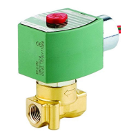
SERIES
8210
8211
DESCRIPTION
Series 8210 valves are 2-way normally closed, internal pilot
operated solenoid valves designed for general service. Valves are
made of rugged forged brass or die cast stainless steel. Series 8210
valves are provided with a general purpose solenoid enclosure.
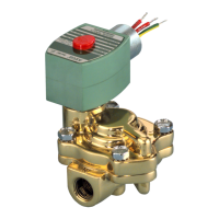
Series EF8210 and 8211 are the same as Series 8210 valves except
that they are provided with an explosionproof/watertight solenoid
enclosure.
Notice: Brass valves are not certifi ed as lead-free under the
Safe Water Drinking Act SWDA 1417 and are not intended
for use on drinking water systems. They are intended for
control of water in industrial applications. Consult ASCO
for valves rated for use in potable water applications.
OPERATION
Normally Open: Valve is open when solenoid is de-energized;
closed when energized.
Manual Operator (Optional)
Valves with suffi x “MO” in catalog number are provided
with a manual operator which allows manual operation
when desired or during an interruption of electrical
power. To operate valve manually, push in knurled cap
and rotate 180°. Disengage manual operator by rotating
knurled cap counterclockwise 180° before operating electrically.
INSTALLATION
Check nameplate for correct catalog number, pressure, voltage,
frequency, and service. Never apply incompatible fl uids or exceed
pressure rating of the valve. Installation and valve maintenance to
be performed by qualifi ed personnel.
Future Service Considerations
Provision should be made for performing seat leakage, external
leakage, and operational tests on the valve with a nonhazardous,
noncombustible fl uid after disassembly and reassembly.
Temperature Limitations
For maximum valve ambient and fl uid temperatures, refer to chart
below. Check catalog number prefi x and watt rating on nameplate.
NOTICE: See separate solenoid installation and maintenance
instructions for information on: Wiring, Solenoid Temperature,
Cause of Improper Operation, Coil or Solenoid Replacement.
Watt
Rating
AC/DC
Catalog
Number
Prefi x
Solenoid
Class
Maximum
Ambient
Temp.
Maximum
Fluid
Temp.
15.4 or 16.1
AC
None, KF,
SF or SC
F
125 °F
(51.7 °C)
180 °F
(82 °C)
HT, KH, ST or
SU
H
140 °F
(60 °C)
180 °F
(82 °C)
16.8
DC
None or HT F or H
77 °F
(25 °C)
180 °F
(82 °C)
Page 1 of 4