Page 1 of 3
50 Hanover Road, Florham Park, New Jersey 07932 www.ascovalve.com
All Rights Reserved.
E176965
Installation & Maintenance Instructions
SERIES
I&M No.V7538
8321
3-WAY INTERNAL PILOT-OPERATED SOLENOID VALVES
3/8I AND 1/4I NPT
NORMALLY CLOSED AND NORMALLY OPEN OPERATION
NOTICE: See separate solenoid installation and
maintenance instructions for information on: Wiring,
Solenoid Temperature, Cause of Improper Operation and
Coil Replacement.
DESCRIPTION
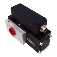
Series 8321 valves are 3-way , internal pilot operated, piston type
solenoid valves. Valves may be provided with a general
purpose/watertight, open frame, or watertight/explosionproof
solenoids.
OPERATION
Normally Open:
Solenoid De-energized: Flow is from Pressure P" to Cylinder A",
Exhaust E" connection is closed.
Solenoid Energized: Flow is from Cylinder A" to Exhaust E",
Pressure P" connection is closed.
Normally Closed:
Solenoid De-energized: Flow is from Cylinder A" to Exhaust E",
Pressure P" connection is closed.
Solenoid Energized: Flow is from Pressure P" to Cylinder A",
Exhaust E" connection is closed.
NOTE: To change from normally closed operation to normally open
operation, consult ASCO.
(CYL)
A
(CYL)
A
(CYL)
A
(CYL)
A
E
(EXH)
E
(EXH)
E
(EXH)
E
(EXH)
P
(PRESS)
P
(PRESS)
P
(PRESS)
P
(PRESS)
NORMALLY CLOSEDNORMALLY OPEN
FLOW DIAGRAMS
DE-ENERGIZED ENERGIZED
DE-ENERGIZED ENERGIZED
IMPORTANT: A minimum operating pressure differential of 10 psi
is required.
Manual Operation
Valves with suffix MO" or MS" after catalog number are provided
with a manual operator which allows manual operation when desired
or during an interruption of electrical power.
CAUTION: For valve to operate electrically, manual
operator stem/lever must be fully rotated counterclockwise.
INSTALLATION
Check nameplate for correct catalog number, pressure, voltage,
frequency, and service. Never apply incompatible fluids or exceed
pressure rating of the valve. Installation and valve maintenance to be
performed by qualified personnel.
Temperature Limitations
Valves with design change letter K" or P" within the catalog number
(example: 8321K004) have a maximum fluid temperature of 180F.
Refer to separate solenoid Installation and Maintenance Instructions
for maximum ambient temperature.
Positioning
This valve is designed to perform properly when mounted in any
position. However, for optimum life and performance, the solenoid
should be mounted vertically and upright to reduce the possibility of
foreign matter accumulating in the solenoid base sub-assembly area.
Piping
Connect piping or tubing to valve according to markings on valve
body. Apply pipe compound sparingly to male pipe threads only. If
applied to valve threads, the compound may enter the valve and cause
operational difficulty. Avoid pipe strain by properly supporting and
aligning piping. When tightening the pipe, do not use valve or
solenoid as a lever. Locate wrenches applied to valve body or piping
as close as possible to connection point.
IMPORTANT: To protect the solenoid valve, install a
strainer or filter, suitable for the service involved, in the inlet
side as close to the valve as possible. Clean periodically
depending on service conditions. See ASCO Series 8600,
8601 and 8602 for strainers.
MAINTENANCE
WARNING: To prevent the possibility of death,
personal injury or property damage, turn off electrical
power, depressurize solenoid valve, and vent fluid to a
safe area before servicing.
NOTE: It is not necessary to remove the valve from the pipeline for
repairs.
Cleaning
All solenoid valves should be cleaned periodically. The time between
cleanings will vary depending on the medium and service conditions. In
general, if the voltage to the coil is correct, sluggish valve operation,
excessive noise or leakage will indicate that cleaning is required. In the
extreme case, faulty valve operation will occur and the valve may fail to
open or close. Clean valve strainer or filter when cleaning the valve.
Preventive Maintenance
Keep medium flowing through the valve as free from dirt and
foreign material as possible.
Periodic exercise of the valve should be considered if ambient or
fluid conditions are such that corrosion, elastomer degradation,
fluid contamination build up, or other conditions that could
impede solenoid valve shifting are possible. The actual frequency
of exercise necessary will depend on specific operating conditions.
A successful operating history is the best indication of a proper
interval between exercise cycles.
Depending on the medium and service conditions, periodic
inspection of internal valve parts for damage or excessive wear is
recommended. Thoroughly clean all parts. If parts are worn or
damaged, install a complete rebuild kit.