503543-001
1
General installation and maintenance instructions
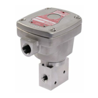
Valves with Positioner
D
- Series Aseptic
2
1
P
•
•
•
•
•
(2)
(1)
3
P
•
•
•
•
•
(2)
(1)
2
1
•
GB
DESCRIPTION (Figs. 1 and 2)
The valves are equipped with different types of operators
depending on the version used.
A Positioner
D
positioning unit made of PA (polyamide) 6/6
GF 30% (glass fibre reinforced) equipped with a metal ca-
ble gland for cable dia. 4,5 - 9 mm is standard fitted on the
valves. It includes a linear potentiometer, a processor and
two pilot valves.
- Single loop control
- Double loop control for positioner with directly connected
external sensor.
APC software for modification of control parameters is available
for download at: www.asconumatics.eu. The APC software is
required for double loop control.
The Positioner
D
with double-loop control is delivered ex works
with factory settings (positioner). The device must be mounted
on the aseptic valve and initialised with these factory settings.
The APC software can be used to set the Positioner
D
to double-
loop control in the Custom Parameters only after initialisation.
Initialisation may only be performed with the factory settings.
The proportional valve is factory-adjusted. The Positioner
D
is equipped with an electronic “shut off” system to exhaust
the pilot chamber at 0 setpoint to ensure that the valves are
tight when closed.
P
p
21
0-10 V
4-20 mA
Fig. 1 Fig. 2
OPERATION (Figs. 1 and 2)
NC – Normally closed: The valve is closed when no pilot pres-
sure is supplied by the positioner to the actuator.
The valve opens when the positioner supplies a pilot pressure.
In the auto-adjust phase, adapt the pilot pressures according
to the actuator:
2 to 3 for an actuator with very low pilot pressure (1,5 b)
3 to 5 bar for an actuator with low pilot pressure (2,5 b)
5 to 7 bar for an actuator with high pilot pressure (4 b)
On loss of power the valve returns to the fail close position
or the disc position is maintained.
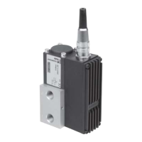
INSTALLATION AND PUTTING INTO SERVICE (Fig. 3)
The device is supplied factory installed and adjusted.
The final installation consists of connecting the electrical and
pneumatic supply; the device is then ready for operation in
accordance with the setpoint values.
The green LED 3 lights up when power is ON.
The bottom LED 4 (orange) lights up when the valve is fully closed.
The top LED 1 (yellow) lights up when the valve is fully open.
A rapidly flashing red LED 2 indicates a device malfunction,
see “Error Definitions” on last page.
Description
ERROR No.
LED 1 LED 2 LED 3 LED 4
OPEN
ERROR
POWER
CLOSED
Hold position
Valve OPEN
Valve CLOSED
Valve moves to open
Valve moves to close
Positioner in initialisation mode
Positioner in manual mode
Setpoint > 20,5 mA / 10,25 V
1
Setpoint < 3,5 mA
2
Positioner not initialised
3
Component error
4
LED on
LED off
LED slow flashing
LED quick flashing
Fig. 3
ELECTRICAL CONNECTION (Fig. 4)
All electrical connections must be made by trained and
qualified personnel only and be in accordance with your local
regulations and standards.
In order to ensure EMC protection, the device must be con-
nected to earth with a shielded cable. On the device side,
the shield must be connected via the metal cable gland and/
or via a shielded connector (M12). On the control side, the
cable shield must have a low-impedance connection to earth.
1) Connection by cable and cable gland
CAUTION:
• Beforestartinganywork,turnofftheelectricalcurrent
and shut off the air supply to power off the components.
Unscrew and remove the cover.
Connect the terminal block (fig 4, no. 1) as indicated below.
Supply voltage 24 V DC.
• Pin1:+24VDCsupply
• Pin2:GNDsupply
• Pin3:Setpoint(0-10Vor4-20mA)
• Pin4:GNDsetpoint
• Pin5:Externalsensorinput(doubleloopoption)
• Pin6:Discpositionfeedback
• Pin7:24VON/OFFoutput(discposition=setpoint)
Fig. 4
503543-001 / A
Availability, design and specifications are subject to change without notice. All rights reserved.