503543-001
3
General installation and maintenance instructions
Valves with Positioner
D
- Series Aseptic
2
1
P
•
•
•
•
•
(2)
(1)
3
P
•
•
•
•
•
(2)
(1)
2
1
•
GB
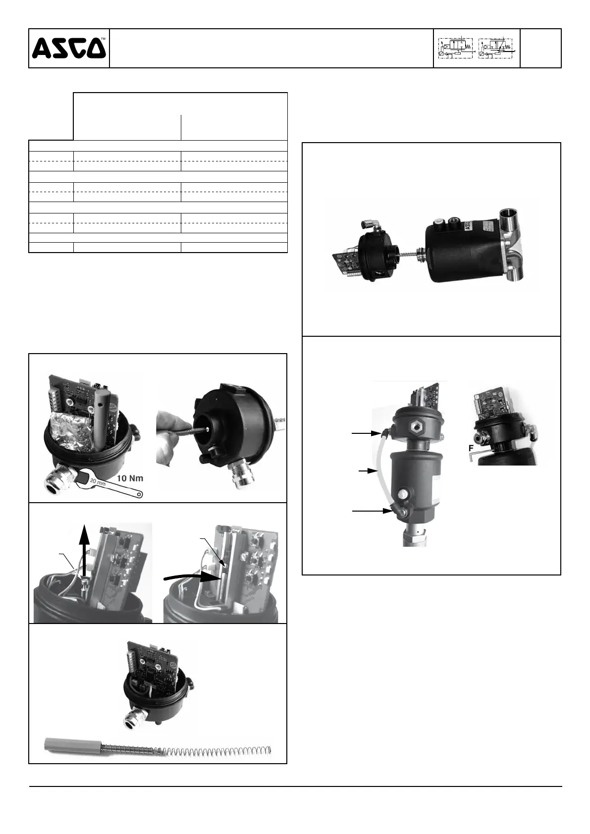
3- Mounting on valve (fig. 14)
a. Make sure that screw F is loose.
b. Assemble the unit onto its support.
c.
Orient pneumatic connection no. 5 so that it faces pilot orifice
no. 9 of the valve and connect tube no. 10 (fig 15).
d. Fix the unit into position with screw F; be sure to observe
a tightening torque of 1,5 Nm (fig. 16).
Fig. 14
Fig. 15 Fig. 16
Rep. 5
Rep. 9
Rep. 10
4- Connections
Make all electrical and pneumatic connections in accordance
with the general instructions.
In case of use with a 4-20 mA setpoint, send a value > 4 mA
(e.g. 5 mA) in order to start the initiation cycle.
2- Preparation of the new unit:
Unit identification
spare parts kit no. (Positioner
D
only
)
cable gland
(câble Ø 5-10 mm)
connection M12
Fail position maintained, single loop
0-10 V 60568108 60569108
4-20 mA 60568308 60569308
Fail close, single loop
0-10 V 60568118 60569118
4-20 mA 60568318 60569318
Fail close, double loop
0-10 V 60568418 60569418
4-20 mA 60568518 60569518
Mounting kit
all C140423 C140423
a. Remove the cover and its seal to gain access to the stem
and its spring (figs. 9 and 13).
b. Put the stem and its spring in place (manually hold the
compressed spring on the stem) (fig. 10).
c.
Clip the end of stem no. 7 into the holder on the potentiometer
by tilting the stem away and placing it back upright (figs. 11
and 12).
d. Re-install the two pneumatic connections from the old unit
on the new unit, or use mounting kit no. C140423 (see
pages with drawings).
Fig. 9 Fig. 10
Fig. 11 Fig. 12
Rep. 7
Rep. 7
Fig. 13
 Loading...