503543-001
2
General installation and maintenance instructions
Valves with Positioner
D
- Series Aseptic
2
1
P
•
•
•
•
•
(2)
(1)
3
P
•
•
•
•
•
(2)
(1)
2
1
•
GB
All screw terminals must be properly tightened prior to op-
eration (be sure to observe a tightening torque of 3 Nm).
The electrical connection is made by a metal cable gland
M16 x 1,5 mm for cable dia. 4,5-9 mm (tightening torque: 3 Nm).
Put the cover and its seal back in place (be sure to observe
a tightening torque of 5 Nm).
2) Connection by M12 connector:
Pin
5
41
32
Single loop Double loop
1 + 24V
2 + Setpoint
3 GND
4 Disc position feedback External sensor input
5 ON/OFF output: 24 V PNP
Positioner
D
, single loop
terminal block
M12
5
41
32
1 + 24 V DC supply 1
2 GND supply 3
3 + Setpoint (0-10 V or 4-20 mA) 2
4 Setpoint GND 3
6 Disc position feedback 4
7 ON/OFF output: 24 V PNP 5
Positioner
D
, double loop
terminal block
M12
5
41
32
1 + 24 V DC supply 1
2 GND supply 3
3 + Setpoint (0-10 V or 4-20 mA) 2
4 Setpoint GND 3
5 External sensor input 4
7 ON/OFF output: 24 V PNP 5
PUTTING INTO OPERATION
Valve installation: See I&M sheets for the series Aseptic 2/2
valves (http://www.asconumatics.eu).
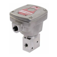
Positioner
D
unit characteristics:
- Pilot fluid: Air or inert gas, filtered 50 µm, unlubricated,
condensate-free and water-free (
- Supply pressure: 4 to 8 bar
-Ambientandpilotuidtemperature:0to+50°C
- Electrical protection: IP66 (EN 60529)
Analog setpoints to be selected when ordering:
- Voltage setpoint 0 – 10 V (200 kΩ input resistance)
- Current setpoint 4 - 20 mA (250 Ω input impedance)
- Supply voltage: 24 V DC ±10%
- Power rating: max. 8,5 W
- Hysteresis: < 2% of max. disc stroke
- Accuracy: < 2% of max. disc stroke
- ON/OFF output: 24 V PNP /max. 500 mA
-External sensor signal (option) = setpoint signal (0-10 V or
4-20 mA)
-Disc position feedback signal = setpoint signal (0-10 V or
4-20 mA)
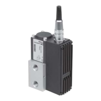
PNEUMATIC CONNECTION (Fig. 5)
Connection: G 1/8 at pressure inlet.
Fig. 5
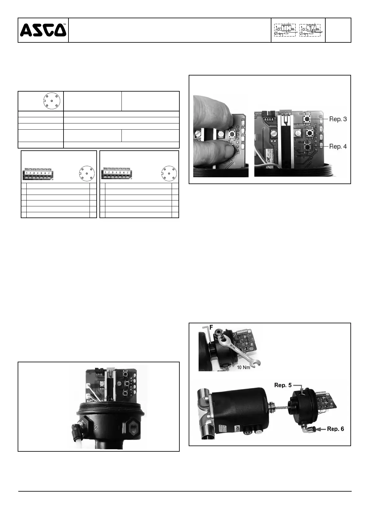
MANUAL OPENING AND CLOSING
It is possible to manually open and close the valve during
normal operation.
Procedure:
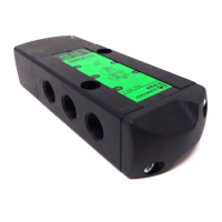
1 – Remove the cover.
2 – To switch to manual mode, simultaneously press the “Open”
button (no. 3) and the “Close” button (no. 4) until the green
LED flashes.
3 – Press the top button to open: The valve will open as
long as the button is pressed, it will stop opening as
soon as the button is released (fig. 7).
Fig. 6 Fig. 7
Or,
Press the bottom button (no. 4) to close: The valve will close
as long as the button is pressed, it will stop closing as soon
as the button is released. (fig. 7)
You can:
- Obtain information on the disc’s position with a voltmeter or
an amperemeter connected to pins 2 and 6.
Exit from the manual mode:
- To exit the manual mode, again simultaneously press buttons
nos. 3 and 4 for 3 to 5 seconds; the disc will automatically
be restored into the setpoint position.
POSITIONER
D
UNIT REPLACEMENT
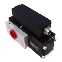
1- Removal of the unit to be replaced (fig. 8)
a. Disconnect and remove all electrical and pneumatic sup-
plies.
b. Disconnect the pneumatic connection to the valve and
remove connector no. 5 (not supplied in the kit).
c. Loosen screw F by several turns to remove the unit from
its support.
d.Removetheunit+stemassemblyandtakecaretoprotect
the stem against damage and bending stress.
e. Remove pneumatic supply connections nos. 5 and 6.
Fig. 8
 Loading...