503543-001
4
General installation and maintenance instructions
Valves with Positioner
D
- Series Aseptic
2
1
P
•
•
•
•
•
(2)
(1)
3
P
•
•
•
•
•
(2)
(1)
2
1
•
GB
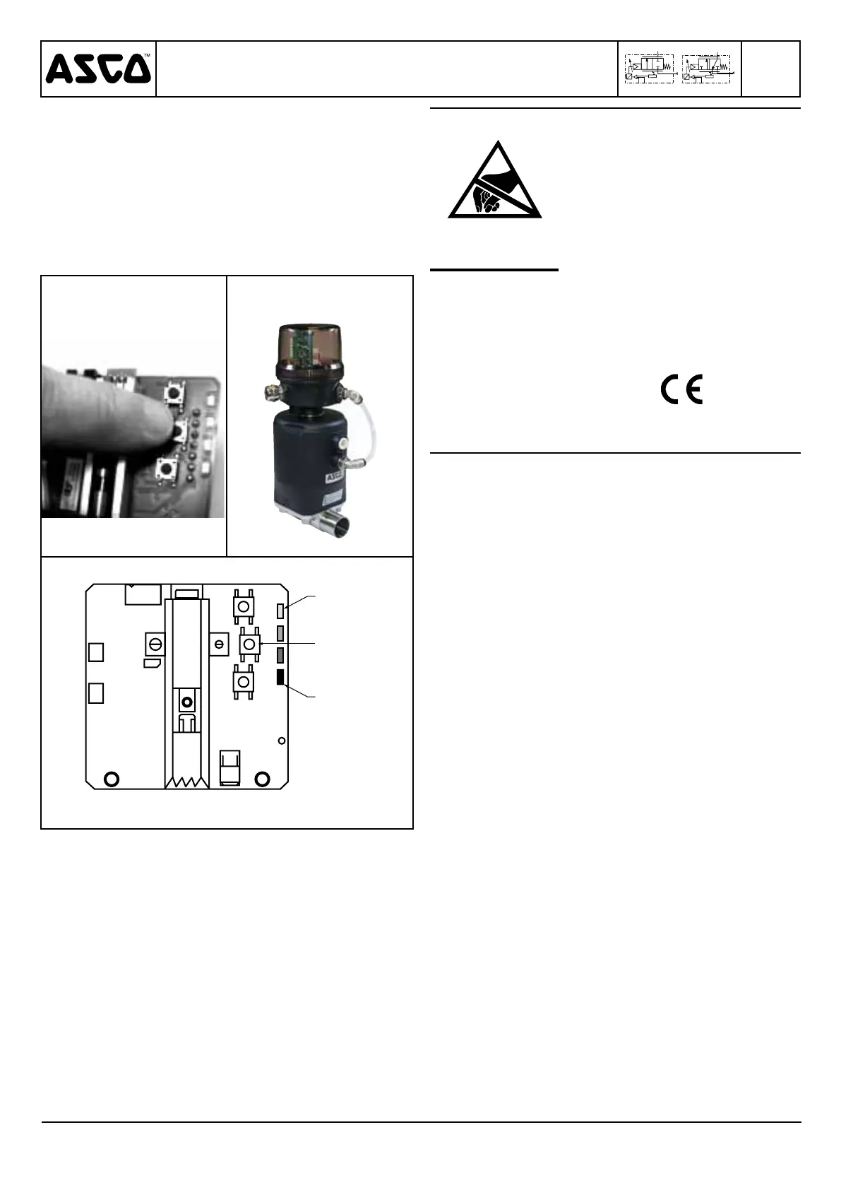
5- Adjustment of the new unit
a. Apply electrical power and air pressure.
b. Press middle button no. 12 for more than 3 seconds until
LED 1 (yellow) and LED 4 (orange) flash to automati-
cally start the initialisation procedure (figs. 17 and 19).
c. Release the button and leave the device to automatically
run the initialisation cycle (several openings and closures).
d. After approx. 1 minute, the valve stops in the preset setpoint
position. If there is no setpoint, the valve closes in airtight
position.
e. Put the cover and its seal back in place; be sure to ob-
serve a tightening torque of 5 Nm.
Fig. 17 Fig. 18
78M05
LED 1
Rep. 12
LED 4
Fig. 19
MAINTENANCE
Prior to any maintenance work or putting into operation,
power off the Positioner
D
, depressurise and vent the
valve to prevent the risk of personal injury or damage
to equipment.
This product complies with the essential requirements
of EMC Directive 2004/108/EC and Low Voltage Directive
2006/95/EC. A Declaration of Conformity is available on
request.
This product contains electronic
components sensitive to electro-
static discharge. An electrostatic
discharge generated by a person
or object coming in contact with
the electrical components can
damage or destroy the product.
To avoid the risk of electrostatic
discharge, please observe the
handling precautions and recom-
mendations contained in standard
EN 100015-1.
Do not connect or disconnect the
device while it is energised.
CAUTION
OBSERVE
PRECAUTIONS
FOR HANDLING
ELECTROSTATIC
SENSITIVE
DEVICES
 Loading...