Do you have a question about the ASCOM BS330 and is the answer not in the manual?
Overview of the BS330 base station, its connection, versions, contents, power sources, and software update capabilities.
Lists the available BS330 base station models and their respective frequency band specifications.
Details the items included in the BS330 base station package, such as the unit, bracket, and screws.
Explains how the base station can be powered via the radio exchange or a local AC-adapter.
Information on the 24 Vdc adapter used for powering the BS330 base station.
Instructions on updating the BS330 base station software remotely using the Cordless System Manager.
Describes the RJ45 modular jacks for data/power and the RJ12 jack for factory testing on the base station.
Explains the meaning of the LED indicators (LED1, LED2) on the BS330 base station for status monitoring.
Requirements for twisted pair cables used for data and power distribution to the base station.
Comprehensive guide for installing the BS330 base station, including mounting bracket fixation and placement.
Step-by-step instructions for securely mounting the BS330 base station bracket to a wall.
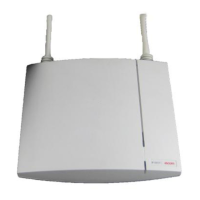
Guidance on mounting the BS330 base station bracket to a ceiling, ensuring correct orientation.
Method for attaching the BS330 base station mounting bracket to poles or beams using straps.
Advice on using cable ducts to route wiring neatly when installing the base station.
Safety recommendation to secure the base station cable to prevent accidental disconnection.
Procedure for preparing and connecting the base station cable to an RJ45 modular jack.
Steps for measuring cable delays, crucial for system initialization with specific hardware.
Note on applying brand labels to the BS330 base station, which must be ordered separately.
Instructions for routing and connecting data and power cables to the BS330 base station.
Final steps for attaching the BS330 base station onto its mounted bracket until it clicks.
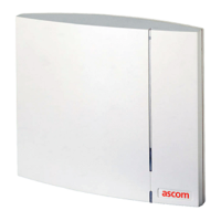
The device described in the manual is the BS330 base station, a component of a DCT1800-GAP cordless system. It functions as a radio transceiver, connecting to a radio exchange via a standard twisted pair cable. The base station can be mounted in various locations, including walls, ceilings, poles, or beams, using an included mounting bracket. For pole or beam mounting, a separate strap or flexible metal band (not included) is required.
The BS330 base station facilitates wireless communication within the cordless system. It receives power and data from the radio exchange through its RJ45 connectors. The base station's operational status and traffic activity are indicated by two LEDs: LED 1 (Green power LED) and LED 2 (Three-colour LED). LED 2 provides detailed status information:
The base station's software can be updated by downloading new software, which is stored in flash memory. This process can be performed without disconnecting the base stations, using the Cordless System Manager (CSM) for Windows.
The BS330 base station comes in several versions, each operating within a specific frequency range:
The base station can be powered by:
It is crucial not to power the base station via the EPP terminals from a local power source and the radio exchange simultaneously, as this would interconnect the two power sources. However, simultaneous powering via data pairs from the radio exchange and a local power source is permissible due to an internal rectifier. The power inlet of the base station (EPP) is insensitive to polarity reversals.
The base station cable must be a twisted pair cable with a minimum of 2 pairs for data lines. Power can also be distributed via these data pairs. A three-pair cable can be used for additional EPP wires to extend the distance between the base station and radio exchange. Data lines of the same twisted pair (e.g., SC0-a and SC0-b) can be interchanged, and the EPP pair is insensitive to polarity reversal. Data pairs themselves should not be interchanged.
Base stations can be mounted vertically or horizontally. When mounting, ensure the base station is not facing large metal objects like heating pipes.
When wall-mounted, cable ducts can be used to route wiring. Minimum distances between cable ducts and the mounting bracket are specified (e.g., 57 mm from the top of the bracket to the top of the duct, 65 mm from the top of the bracket to the ceiling, 75 mm from the side of the bracket to the side of the duct, 125 mm from the bottom of the bracket to the bottom of the duct).
For safety, secure the base station cable approximately 30 cm from the base station to prevent it from being pulled out if the base station drops.
Cut the base station cable to the correct length and connect it to an RJ45 modular jack. If cables need to enter centrally from above, guide them through the recess in the middle of the base station. Plug the data cable's modular jack into one of the data/power connectors. If using an AC-adapter, plug its modular jack into a data/power connector and the AC-adapter into a wall outlet.
Hold the base station flat against the mounting bracket and slide it downwards until it clicks into place.
After installation, base stations must be initialized using the cordless system manager.
This is necessary when the base station is connected to specific CLU or SLU boards (REX-BRD0014, REX-BRD0015, or REX-BRD0026 with revision lower than R2A). After all base stations are installed, cable delays must be measured to program them into the system at initialization.
Brand labels are not included in the box and must be ordered separately. They are to be stuck in the front cover recess of the base station.
| Brand | ASCOM |
|---|---|
| Model | BS330 |
| Category | Accessories |
| Language | English |