P/N PM000223A • Rev. 1 • ISS 9 August 2017 6
Installation Manual
NU-Series Hardware
Introduction
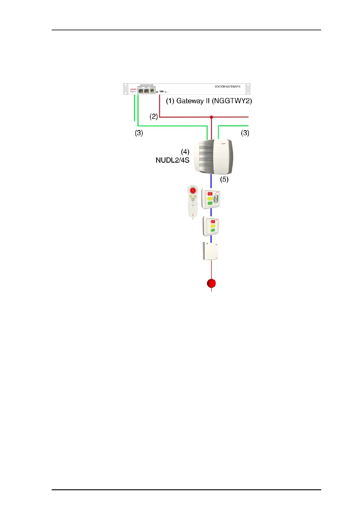
Figure 4 Active room bus with dome light and active room modules
Legend:
(1) Gateway II
(2) Power from Gateway II to hallway devices and room modules
(3) Hallway bus
(4) Dome Light (NUDL4/NUDL2)
(5) Active room bus
Each NUDL dome light supports two room buses. The maximum number of modules that
can be connected to the room bus can vary based the on total power consumption of the
connected modules and the length of the bus cable. However, the software limits this to a
total of sixteen modules.
1.4.4 Addressing Active Room Bus Modules
Like the hallway bus devices, active modules on a room bus can be addressed using either
DIP switches or the Software Configuration Tool for serial number-based addressing.
However, you must follow the same addressing method as used to address the hallway
bus devices. The address range for active room bus modules is 0-7.