P/N PM000223A • Rev. 1 • ISS 9 August 2017 45
Installation Manual
NU-Series Hardware
IP Devices
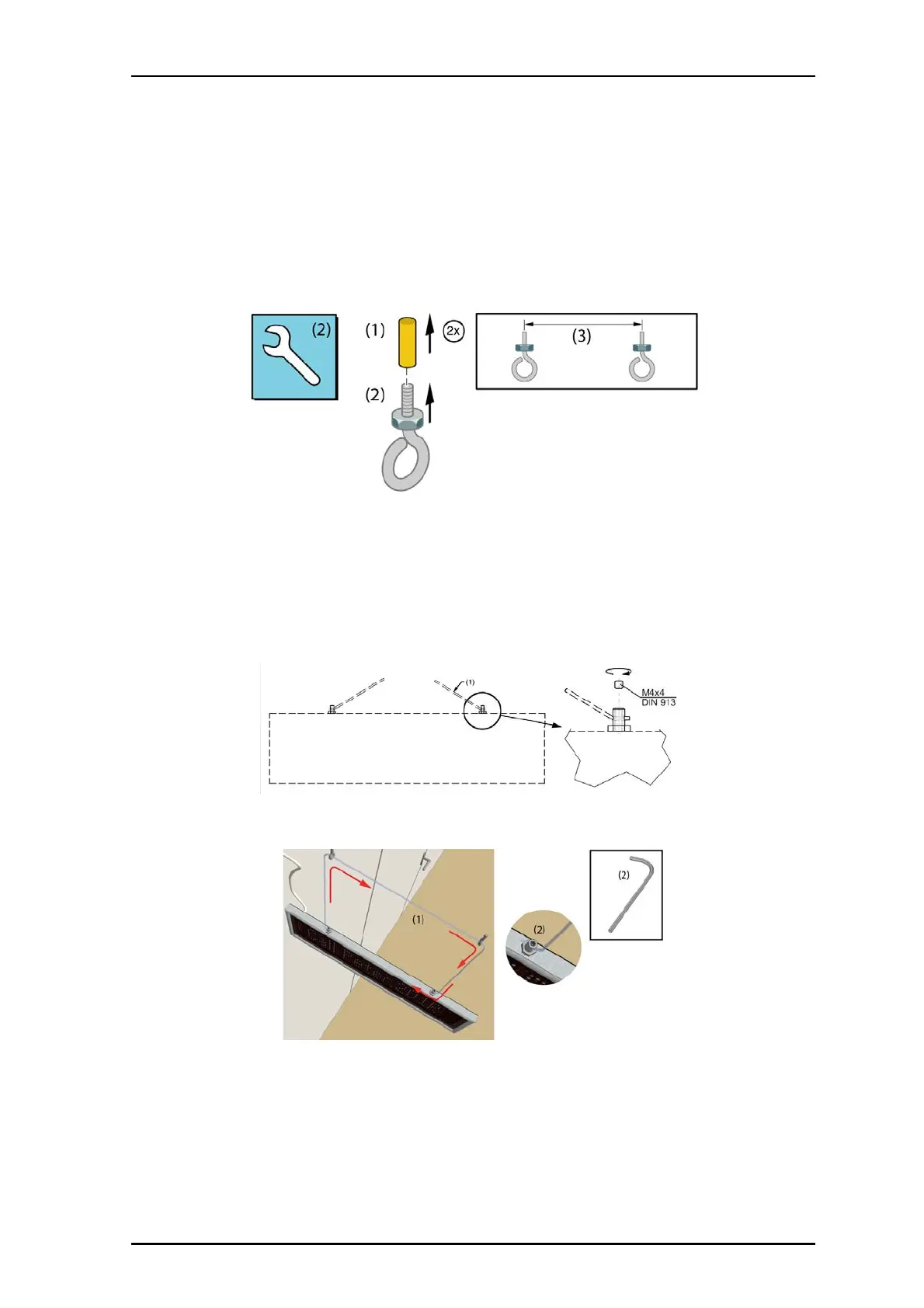
To mount the display from a ceiling:
1. Ensure that the LAN cable is connected to the corridor display. See "5.4.5, Connecting
the LAN Cable" on page 43.
2. Drill two screw holes in the ceiling 235mm (9.25in.) apart for the type of eyelet screws
(not included) that will be used to support the display device.
3. Mount the two eyelet screws. Use anchors to secure the screws, if necessary.
Legend:
(1) Ceiling anchor
(2) eye bolt
(3) 235mm (9.25in.)
4. On the corridor display fixtures, slightly unscrew the two hex screws at the top. On one
end pull the nylon line suspension through the hole of the display fixture and tighten
the hex screw using a hex key.
5. Pull the suspension nylon line through the two eyelet fixtures in the ceiling and fix the
line at the other end of the display.
6. Connect the Ethernet cable from the corridor display to the outlet. See
"5.4.5, Connecting the LAN Cable" on page 43.