EasyManuals Logo

ASCOM NU Series User Manual

ASCOM NU Series
137 pages
To Next Page IconTo Next Page
To Previous Page IconTo Previous Page
Page #93 background imageLoading...
Page #93 background image
P/N PM000223A • Rev. 1 • ISS 9 August 2017 85
Installation Manual
NU-Series Hardware
Room Modules
2 of 2 P/N PM000157A • Rev. 1.00 • ISS 4/13/17
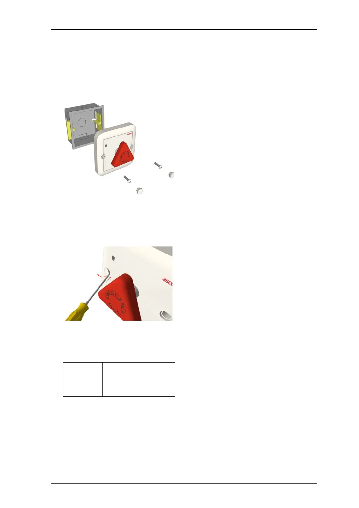
4. Align the pull switch over the backbox, and then insert the
screws though the holes on the pull switch and into the
backbox. Tighten the screws.
5. Insert the screw hole covers into the pull switch.
Removal
To remove module from the backbox:
With a small blade screwdriver (2mm), carefully remove the
screw hole covers.
6. Remove screws.
7. Remove module.
8. Disconnect RJ-45 Connectors.
Specifications
Wire/terminations
Cat 5/5e/6/7 U/UTP with RJ-45
connectors.
Compatible
electrical boxes
European Union, United Kingdom:
Standard plastic or metal back box
with mounting holes: 60mm
(2.36in.)

Table of Contents

Questions and Answers:

Question and Answer IconNeed help?

Do you have a question about the ASCOM NU Series and is the answer not in the manual?

ASCOM NU Series Specifications

General IconGeneral
BrandASCOM
ModelNU Series
CategoryNetwork Hardware
LanguageEnglish

Related product manuals