Module Connectors
INSTALLATION GUIDE
Bedside Module (NUBM3-HE)
4 Module Connectors
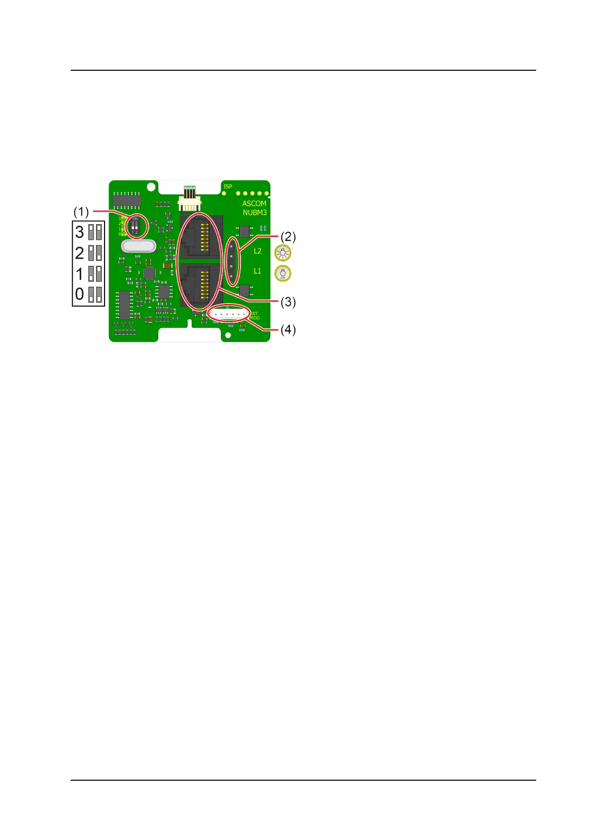
The module includes two RJ45 jacks for room bus connections, a connector for light relays, a connector for
the NUBM3X-HE extension module, and DIP switches for room bus addressing. Figure 1 shows the
connectors and DIP switches on the back of the module.
Figure 1. Module connections
Legend
1. DIP switches for room bus addressing
2. 4–pole connector for light relays
3. 2 x RJ45 connections to room bus
4. 6–pole connector to NUBM3X–HE extension module
4.1 Setting the Room Bus Address
The room bus address is a unique number assigned to a room module when modules of the same type are
attached to the room bus.
If you do not use DIP switches to set the room bus address, be sure all the DIP switches are in the OFF
position on the back of the module.
To set the DIP switches:
1. Set the DIP switches for the correct room bus address.
2. Using a small screwdriver, gently slide the switch up for “ON” or slide it down for “OFF”.
5
TD 93505EN / 28 February 2022 / Ver. A