TD 90227GB
2006-09-18/ Ver. C
System Installation
On Site Paging System
13
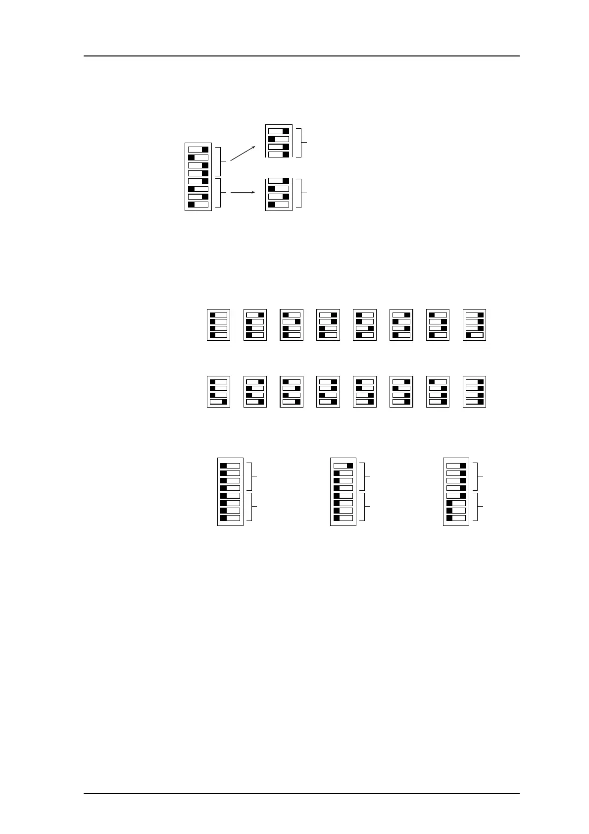
The address consists of two hexadecimal digits that are selected by the eight sections of
the address switch. Sections 5-8 of the switch select the first (most significant) digit and
sections 1-4 select the second digit.
1
Sections 1 - 4
second hex digit (D)
Hex address 5 D
OFF ON
1
88
4
5
Sections 5 - 8
first hex digit (5)
Figure 12. Address switch.
The two hex digits provide a total of 256 possible addresses in the system. The figure
below shows how to set the hex digits 0-F.
OFF ON
Hex 0
OFF ON
Hex 8
Hex 1
Hex 9
Hex 2
Hex A
Hex 3
Hex B
Hex 4
Hex C
Hex 5
Hex D
Hex 6
Hex E
Hex 7
Hex F
1
OFF ON
Hex 0
Hex address 00
8
Hex 0
1
OFF ON
Hex 1
Hex address 01
8
Hex 0
1
OFF ON
Hex F
Hex address 1F
8
Hex 1
Examples:
Figure 13. Hexadecimal address settings.
The Central Unit always has address 00 and other modules can then be addressed in
ascending sequence. Each address must be unique within the installation regardless of
which bus it is connected to. Transmitters in non-speech systems must have hex 0 as the
first (most significant) digit unless sequential transmission is used.
Note: In speech systems the transmitters must be in the address range for speech
transmitters (hex address 80-FF).