TD 90227GB
2006-09-18/ Ver. C
System Installation
On Site Paging System
6
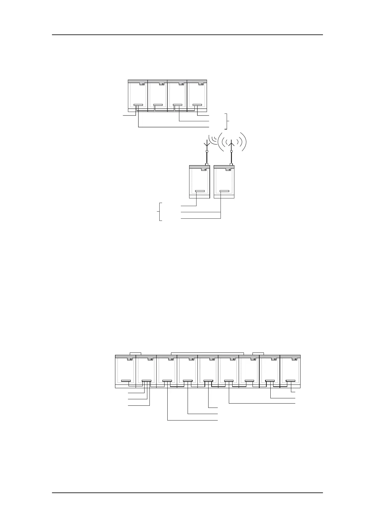
3 km max total length is not exceeded. Each Reference Module and Bus Amplifier has two
FL-bus outputs. The D- and SP/FL-buses must be correctly polarized.
A-bus
R-line
FL-bus
D-bus
Central
Unit
PBX
Interface
Reference
Modul
Receiver
Interfac
e
to terminal site
R-line
FL-bus
D-bus
to central site
Fixed
Receiver
Terminal
Transmitter
Figure 4. System solution: 2-way speech, private lines without modem.
3.3 With Modem to Transmitters
Data and Speech modem introduces delay in the transmitter signal. Transmitter signals “in
the air” will differ and cause distortion in areas of overlapping coverage. A basic rule in
planning an installation is to delay the signals to transmitters equally.
The transmitter code on the D-bus is always generated by the Central Unit. Be sure that
the same number of modem-pairs are used between the Central Unit and each Terminal
transmitter. Several Terminal transmitters can be connected to one Data modem if the
location is suitable.
Synchronize the data modems for the D-bus, see the figure below:
Reference
Module
Control Synchronizing D-line
Delayed buses
direct to terminal site
A-bus
SP-bus
D-bus
System bus to
other units
SP-line
A-line
D-line
Lines via modem
at terminal site
R-line
D-bus
FL-bus
Central
Unit
Data
Modem
Data
Modem
Speech
Modem
Modem
Compensator
Data
Modem
Data
Modem
Receiver
Interface
Figure 5. Private lines with Speech Modem.
Speech signals may come from several different units, for example PBX Interface, Receiver
Interface or Control Keyboard. If speech modems are used with any transmitters, the
modem compensator must be used at those terminal sites where speech is fed into the