TD 90227GB
2006-09-18/ Ver. C
System Installation
On Site Paging System
7
system. The Modem Compensator delays speech that is fed in locally by an amount
equivalent to the delay produced in a speech modem-pair with up to 3 km cabling
between them. The output signal from the Modem Compensator is DFL, “Delayed
Frequency Lock”, and has the same electrical characteristics as the FL-bus. If necessary,
DFL can be amplified by the Bus Amplifier. DFL is connected to the speech bus in the
Terminal Transmitter. Several modem compensators can be connected in series to
compensate for several modem-pairs in series.
DFL
R-line
D-line
SP-line
A-line
A- ,B- ,SP-bus
Speech
Modem
Modem
Compensator
Fixed
Receiver
Terminal
Transmitter
Data
Modem
Receiver
Interface
Data
Modem
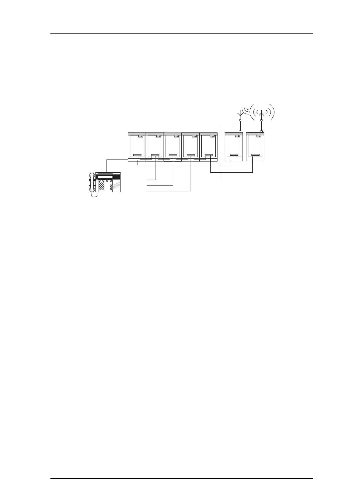
Figure 6. Terminal site with SP-bus.
4 Receivers
Talk-back Receivers are always connected to a RI (Receiver Interface), which in turn is
connected to the A- and SP-buses. Up to four receivers may be connected to the same RI,
each with a separate twisted-pair that must not exceed 1 km. Move the RI closer to the
receivers if the distance exceeds 1 km or use modems to extend the A-, B- and SP-buses of
the RI.
Note that the twisted-pair (R-line) between each receiver and its interface is not included
in the system modular bus and must therefore be connected separately, even when the
units are mounted together. When the Receiver is not activated, this line always carries a
quality tone of about 2.4 Vp-p measured between L1 and L2. When the receiver is