TD 92022EN
3 July 2013 / Ver. G
Installation Guide
H/U952T Terminal Transmitter
19
2 Slide nut, clamp rings and gasket onto cable.
3 Push shank cone between braid and cable sheath until stop (2).
4 Insert cable into housing and screw on the nut.
5 Solder the inner conductor (3).
IMPORTANT: Overheating during soldering ma
y damage insula
tion between inner
conductor and shield resulting in negative effects on cable.
6 Check with ohmmeter for short circuit between connecto
r body and inner conductor.
NOTE: If the cable is connected to a dc-grounded antenna,
disconnect it before making this
check.
7 Insert washer and screw (3).
When connecting the antenna cable to MPT-50 P
ower Di
vider and Slave transmitters, the
connector PL259 (UHF) is used.
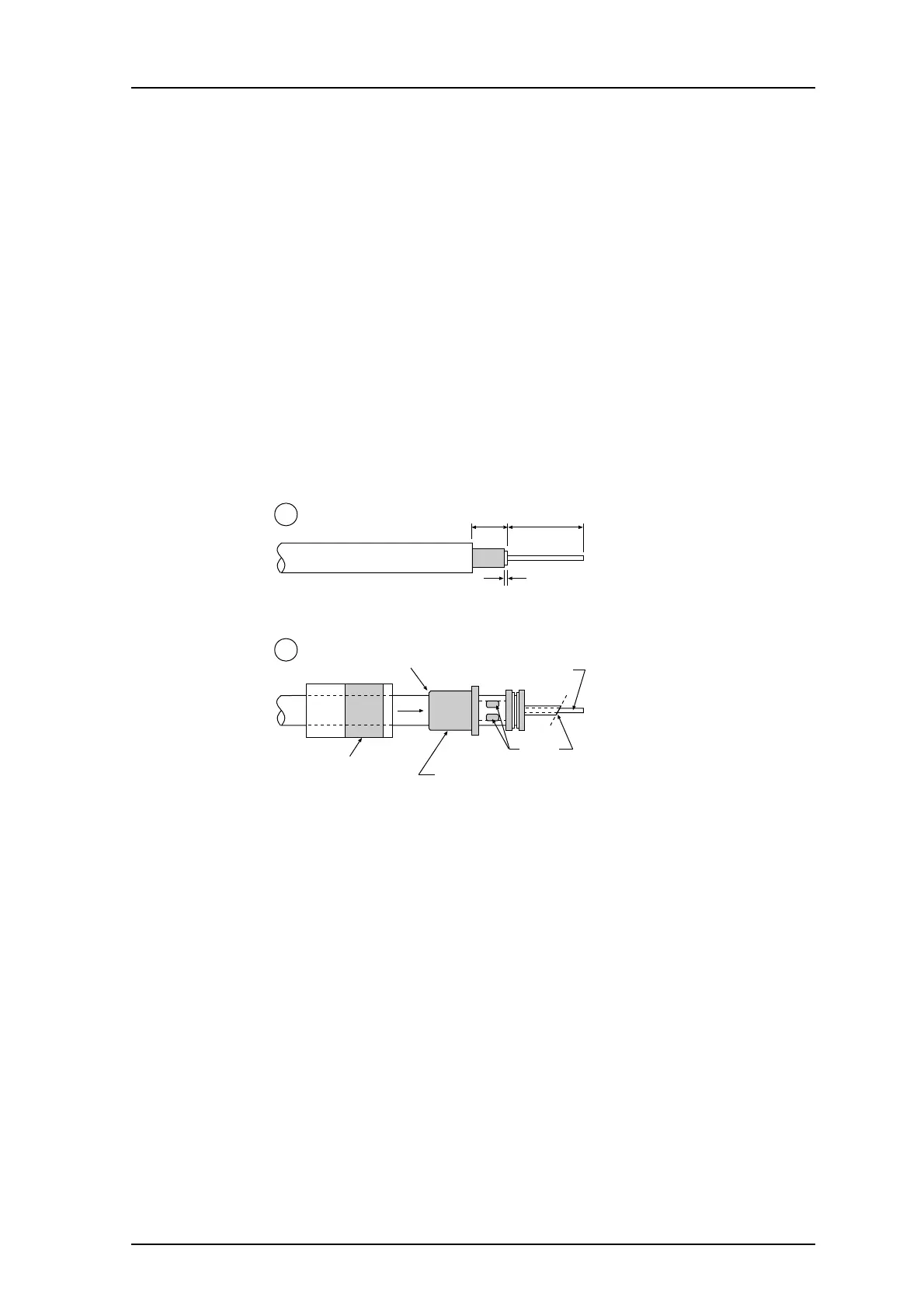
Assemble PL259 Coax Connector as follows:
1
2
cut before
soldering
Coupling
ring
Connector body
(dimensions in mm)
820
1
screw coupling
ring onto body
solder
1 Cut and strip cable as shown in figure at (1).
2 Slide coupling ring onto cable and screw connector body onto cabl
e (2).
3 Solder braided shield to body through the two solder holes.
IMPORTANT: Overheating during soldering may damage insula
tion between inner
conductor and shield resulting in negative effects on cable.
4 Cut inner conductor diagonally as shown and solder to connector.
5 S
crew coupling ring onto body.
6 Check with ohmmeter for short circuit between connecto
r body and inner conductor.
NOTE: If the cable is connected to a dc-grounded antenna,
disconnect it before making this
check.
 Loading...

