Ascon Tecnologic - e33B - OPERATING INSTRUCTIONS - PAG. 12
5.10.1 Temperature alarms
The temperature alarm works according to Pr1 or AU probes
measurement, the type of alarm set in the parameter AAy the
alarm thresholds set in parameters AHA (maximum alarm)
and ALA (minimum alarm) and the relative differential AAd.
Through parameter AAy it is possible to set the alarm thresh-
olds AHA and ALA as absolute or relative to the active Set
Point, must be related to Pr1 or Au probes and if the message
Hi (High alarm) and Lo (Low Alarm) are to be displayed (or
not) at alarm intervention.
Depending on the desired alarm operating mode, parameter
AAy
can be set as:
1 Absolute alarms referred to probe Pr1, displays Hi/Lo;
2 Relative Alarms referred to probe Pr1, displays Hi/Lo;
3 Absolute alarms referred to probe Au, displays Hi/Lo;
4 Relative Alarms referred to probe Au, displays Hi/Lo;
5
Absolute alarm referred to probe Pr1, displays no labels;
6
Relative alarm referred to probe Pr1, displays no labels;
7
Absolute alarm referred to probe Au, displays no labels;
8
Relative alarm referred to probe Au, displays no labels
.
Using some parameters it is also possible to delay the ena-
bling and the intervention of these alarms.
These parameters are:
APA
Temperature alarm exclusion time on switching ON the
instrument if the instrument is in alarm status when it
is switched ON. If the instrument is not in alarm status
when it is switched on the time APA it is not considered.
AdA Temperature alarm exclusion time at the end of de-
frost cycle (and, if programmed, after the draining) or
after a continuous cycle.
AAt Temperature alarms delay activation time. Tempera-
ture alarms are enabled at the end of the exclusion
times and are activated after the AAt time when the
temperature measured by the probe exceeds or goes
below the respective maximum and minimum alarm
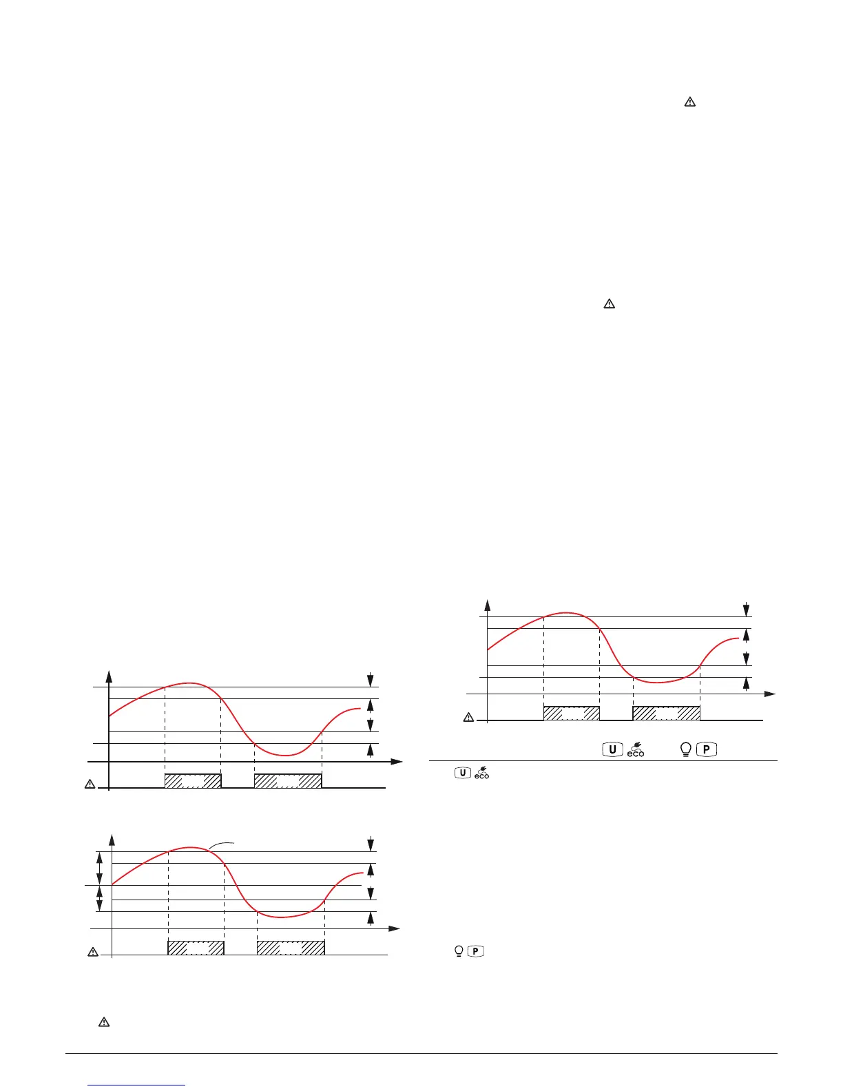
thresholds. The alarm thresholds are those set at
parameters AHA and ALA when the alarms are set as
absolute (AAy = 1, 3, 5, 7).
Temp.
AHA
AAd
time
AL
ALA
AAd
offoffoff
ON ON
Hi Lo
Pr1
or they assume the values [SP + AHA] and [SP + ALA]
if the alarms are relative (AAy = 2, 4, 6, 8).
AHA
SP
ALA
offoffoff
ON ON
Hi Lo
AL
AAd
AAd
Temp.
time
Pr1
The maximum and minimum temperature alarms can be disa-
bled by setting the related parameters AHA and ALA = oF.
The temperature alarms are signalled lighting up the alarm
LED ( ) and, if configured, also with the buzzer.
5.10.2 External alarm from digital input
The instrument can signal an alarm external to the instrument
using the digital input setting iFi = 4 or 5. The instrument
signals the alarm turning ON the
alarm LED ( )
and display-
ing AL label alternated to the variable set with parameter Ids.
Mode iFi = 4 operates no action on the control output, while
iFi = 5 deactivates the control output at digital input intervention.
5.10.3 Open door alarm
The instrument can signal the open door alarm coondition using
the digital input setting iFi = 1, 2 and 3. As the digital input is
activated, the instrument signals that the door is open showing
on the display the oP label alternated to the variable set with
parameter ids.
After the delay set with parameter AoA the instrument signals
the Open Door alarm with the configured devices (buzzer and/
or Output), lighting up the LED while showing the oP label.
At the open door alarm intervention are also re-activated the
inhibited outputs (compressor).
5.10.4 Mains voltage alarms
The instrument can automatically disable the control outputs
when the mains voltage, measured by the instrument through
its power supply, is lower or higher than the values set at
parameters:
ULU Low voltage alarm (expressed as V x 10);
UHU High voltage alarm (expressed as V x 10).
When the alarm triggers and after the delay programmed to
the UUd parameter, the instrument disables the control out-
puts, signals the alarm by activating the configured device
(output and/or buzzer) and shows HU (high voltage alarm), or
LU (low voltage alarm) on the display alternated to the vari-
able set with dS parameter.
If the voltage measurement is not correct, it can be changed
with an offset that can be set using the UOU parameter.
UHU
e.g. 250 V
ULU
e.g. 200 V
offoffoff
ON ON
HU LU
AL
10 V
10 V
Volt
time
V
5.11 Function of keys / and /
The / key function can be defined using the tUF param-
eter to perform the following functions:
oF The key carries out no function;
1 Pressing the key for at least 1 s, is possible to enable/
disable the ECO operating mode. Once the selection has
been made, the display shows for about 1 s the active Set
Point code (SP1, SP2, SP3 o Eco) and its value. When
the instrument esits the ECO operating mode, it returns at
the same operating mode it was using at ECO enabling;
2 Pressing the key for at least 1 s is possible to switch the
instrument from ON to Stand-by state and vice-versa.
The / key function can be defined using the tFb param-
eter to perform the following functions:
oF The key carries out no function;
1 Pressing the key for at least 1 s, is possible to enable/dis-
able the L1 light output or the auxiliary output, if config-
ured as oFo = 2.