EasyManua.ls Logo

Ascon tecnologic e33B User Manual

Ascon tecnologic e33B
19 pages
To Next Page IconTo Next Page
Page #1 background imageLoading...
Page #1 background image
Ascon Tecnologic - e33B - OPERATING INSTRUCTIONS - PAG. 1
e33B
DIGITAL ELECTRONIC
TEMPERATURE CONTROLLER
WITH DEFROSTING FUNCTION
OPERATING INSTRUCTIONS
Vr 02 (ENG) - 18/10 - cod.: ISTR-Me33BENG02
ASCON TECNOLOGIC S.r.l.
Viale Indipendenza 56, 27029 - VIGEVANO (PV) ITALY
Tel.: +39 0381 69871 - Fax: +39 0381 698730
http:\\www.ascontecnologic.com
info@ascontecnologic.com
PREFACE
This manual contains the information necessary for
the product to be installed correctly and also instruc-
tions for its maintenance and use; we therefore recom-
mend that the utmost attention is paid to the following
instructions and to save it
This document is the exclusive property of Ascon Tecnologic
S.r.l. which forbids any reproduction and divulgation, even
partially, of the document, unless expressly authorized.
Ascon Tecnologic
S.r.l. reserves the right to make any formal
or functional changes at any moment and without any notice.
Ascon Tecnologic S.r.l. and its legal representatives do not
assume any responsibility for any damage to people, things
or animals deriving from violation, wrong or improper use or
in any case not in compliance with the instrument features.
Whenever a failure or a malfunction of the device
may cause dangerous situations for persons, thing
or animals, please remember that the plant has to be
equipped with additional electromechanical devices
which will guarantee safety.
1. INSTRUMENT DESCRIPTION
1.1 General description
The model e33B is a microprocessor based digital electronic
temperature controller that is typically used in cooling applica-
tions with ON/OFF temperature control and defrost control
at time intervals, by arrival at temperature or by length of time
of continuous compressor operation through stopping the
compressor, electric heating or hot gas/cycle inversion.
The controller is equipped with special defrost optimization
functions and with other functions that can be used to obtain
energy savings from the controlled system.
The instrument has up to 3 relay outputs and up to 3 NTC
temperature probes inputs one of which can be config-
ured as digital input.
The instrument has an internal buzzer for the acoustic
alarms signalling and a voltage alarm system that deacti-
vates the outputs if the mains voltage is too high/low.
The 3 outputs can be used to control the compressor or the
Index
1. Instrument description ............................................... 1
1.1 General description ........................................................... 1
1.2 Front panel pescription ..................................................... 2
2. Programming ............................................................... 2
2.1 Fast Normal Set Point Programming.................................2
2.2 Standard mode parameters programming ........................ 3
2.3 Parameter protection using a Password ........................... 3
2.4 Customized mode parameter programming
(parameters programming level) ....................................... 3
2.5 Reset parameters to default value .................................... 3
2.6 Keyboard lock function ......................................................3
2.7 Variables display ............................................................... 4
3. Usage warnings ........................................................... 4
3.1 Admitted use ..................................................................... 4
4. Installation warnings ................................................... 4
4.1 Mechanical mounting ........................................................ 4
4.2 Dimensions [mm] .............................................................. 4
4.3 Electrical connections ....................................................... 5
5. Functions ..................................................................... 5
5.1 ON/Stand-by function ........................................................5
5.2 Normal, Economic and Turbo operation ............................ 5
5.3 Measure and display configuration ................................... 6
5.4 Digital input configuration .................................................. 7
5.5 Outputs and buzzer configuration ..................................... 7
5.6 Temperature control .......................................................... 8
5.7 Compressor protection function and power-on delay ........ 8
5.8 Defrost control ................................................................... 9
5.9 Evaporator fans control ................................................... 11
5.10 Alarm functions ............................................................... 11
5.11 Function of keys / and / ................................ 12
6. Accessories ............................................................... 13
6.1 Parameters configuration by “A01” ..................................13
7. Programmable parameters table .............................. 14
8. Problems, maintenance and warranty ..................... 17
8.1 Notifications .................................................................... 17
8.2 Cleaning .......................................................................... 17
8.3 Disposal .......................................................................... 17
9. Warranty and Repairs ............................................... 17
10. Technical data ............................................................ 17
10.1 Electrical characteristics ................................................. 17
10.2 Mechanical characteristics .............................................. 17
10.3 Functional features ......................................................... 18
11. Instrument ordering code ......................................... 18
Question and Answer IconNeed help?

Do you have a question about the Ascon tecnologic e33B and is the answer not in the manual?

Ascon tecnologic e33B Specifications

General IconGeneral
Protection ClassIP65 (front)
Supply voltage24 V AC/DC
InputThermocouple, RTD
OutputRelay, SSR
Control modePID, On/Off
Control AlgorithmPID
DisplayLED
Operating temperature0°C to 50°C
MountingPanel mounting
CommunicationNo

Summary

Preface

Instrument Description

General Description

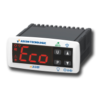
Overview of the microprocessor-based digital electronic temperature controller model e33B and its primary applications.

Front Panel Description

Details the components and layout of the instrument's front panel, including keys and status LEDs.

Programming

Fast Normal Set Point Programming

Sets the regulation Set Point using parameters EEd=1 or EEd=2 for quick and easy adjustment.

Standard Mode Parameters Programming

Procedure to access and modify instrument parameters when password protection is disabled.

Parameter Protection Using a Password

Enables setting a password to protect instrument parameters from unauthorized changes.

Customized Mode Parameter Programming

Allows selective parameter accessibility without password entry via dp LED indication.

Reset Parameters to Default Value

Restores all instrument parameters to factory default settings using a specific password.

Keyboard Lock Function

Prevents accidental changes by locking the keyboard after a period of inactivity.

Variables Display

Allows viewing all measurement and operating variables by simultaneously pressing specific keys.

Usage Warnings

Admitted Use

Specifies the intended application, environmental conditions, and safety precautions for instrument use.

Installation Warnings

Mechanical Mounting

Guidelines for panel mounting, gasket use, and avoiding environments with high humidity or dirt.

Dimensions

Provides detailed mechanical dimensions and panel cut-out specifications for the instrument.

Electrical Connections

Instructions for wiring the instrument, emphasizing safety, overload protection, and cable insulation.

Electrical Wiring Diagram

Visual guide for connecting power supply, inputs, outputs, and internal buzzer terminals.

Functions

ON/Stand-by Function

Describes how to switch the instrument between active operation (ON) and standby mode using keys or digital input.

Normal, Economic and Turbo Operation

Explains the pre-set Set Points (Normal, Eco, Turbo) and their associated hysteresis for different operating modes.

Normal/Eco Operation Selection

Details automatic and manual selection of Normal/Eco modes based on door status or digital input for temperature management.

Turbo/Normal/Eco Mode Selection

Manual and automatic selection of Turbo mode for temperature recovery after cooling or Eco cycles.

Measure and Display Configuration

Configuration of units, resolution, calibration, and selection of the primary displayed variable.

Digital Input Configuration

Defines functions for the digital input, including door opening, alarms, and mode selection for enhanced control.

Outputs and Buzzer Configuration

Configuration options for relay outputs (compressor, defrost, fans, auxiliary) and the internal buzzer's behavior.

Temperature Control

Explains ON/OFF temperature control modes (Cooling, Heating, Neutral Zone) based on probes and set points.

Compressor Protection and Power-On Delay

Details time controls to prevent repeated compressor start-ups and manage power-on delays for system longevity.

Defrost Control

Manages defrost cycles for efficiency, including types, activation modes, and interval settings.

Starting Automatic Defrosts

Methods for initiating automatic defrosts: by interval, evaporator temperature, or compressor runtime.

Defrost by Regular Interval Time

Setting defrost intervals based on real-time, compressor operation time, or compressor stop.

Dynamic Defrost Intervals System

Dynamically adjusts defrost intervals based on thermal exchange performance to reduce unnecessary cycles.

Defrost by Evaporator Temperature

Initiates defrost based on evaporator probe temperature falling below a programmed threshold.

Defrost by Continuous Compressor Running Time

Starts defrost after continuous compressor operation, indicating potential thermal exchange issues.

Manual Defrost

Procedure to manually start or stop a defrost cycle using the keys for immediate control.

End of Defrosts

Defines how defrost cycles conclude: by time, evaporator temperature, or inhibition for proper operation.

Intervals and Defrost Duration with Evaporator Probe Error

Defines defrost intervals and duration when the evaporator probe is faulty or in error.

Display Lock During Defrost

Configures display behavior during defrost, allowing locking or continuous display of Pr1 probe readings.

Evaporator Fans Control

Controls evaporator fans based on compressor status, temperature, and defrost parameters for optimal airflow.

Alarm Functions

Details alarm conditions (probe errors, temp alarms, external, door open) and their signaling methods.

Temperature Alarms

Configures temperature alarm thresholds (max/min), type (absolute/relative), and delay parameters.

External Alarm from Digital Input

Signals external alarms via digital input, affecting alarm LED, display, and control outputs.

Open Door Alarm

Detects and signals open door conditions using the digital input, activating alarms and outputs.

Mains Voltage Alarms

Monitors mains voltage for low/high levels, disabling outputs and signaling alarms for system protection.

Function of Keys U and QP

Defines the programmable functions for the U and QP keys, including Eco mode, Stand-by, and showcase light control.

Accessories

Parameters Configuration by A01

Using the A01 device for serial programming and PC connection via USB for parameter configuration.

Programmable Parameters Table

Set Points and Measurement Configuration

Details parameters for Set Points (SPH, SPE, SP1-3) and input/measurement configuration (unit, filter, calibration).

Function Logic and Control Parameters

Covers parameters for digital input logic, Eco mode, temperature control, defrost, and compressor protection.

Defrost and Fan Control Parameters

Parameters related to defrost activation, duration, types, and evaporator fan control logic.

Compressor Protection and Output Delay Parameters

Parameters for compressor protection delays, output activation/deactivation, and power-on delays.

Alarm and Output Function Parameters

Parameters for temperature alarms, output functions, buzzer modes, and auxiliary output control.

Key Functions, Lock, Filters, and Voltage Parameters

Parameters for key functions, keyboard lock, temperature filters, and mains voltage monitoring.

Problems, Maintenance, and Warranty

Notifications

Lists error messages (probe errors, memory errors) and other status messages for troubleshooting.

Cleaning

Provides guidelines for safely cleaning the instrument using a slightly wet cloth and avoiding abrasives.

Disposal

Instructions for disposing of the appliance in compliance with local waste regulations.

Warranty and Repairs

Technical Data

Electrical Characteristics

Specifies power supply, consumption, inputs, outputs, and protection ratings of the instrument.

Mechanical Characteristics

Details housing material, dimensions, weight, mounting, connections, and operating conditions.

Functional Features

Instrument Ordering Code

Related product manuals