Ascon Tecnologic - K__V - Indicators - ENGINEERING MANUAL - PAG. 2
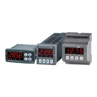
2.1.3 K48V Series
SSR
RELAYS
NO
(M ax 20 mA)
PTC
NTC
ext.
gen.
OUT12VDC
SUPPLY
0..50/60 mV
0/4..20mA
0/1..5 V
0/2..10V
ACTIVE
0..1 V
ACTIVE
PASSIVE
(2 wires)
4..20mA
4..20mA
4
Pt100
TC
INPUT
DIN1
21 3 75 6 8
C
9 10
OUT2
NO
11
C
12
OUT1
RelayOUT3: 5A-AC1 (2A-AC3) 250VAC
SSR:8mA /8VDC
Relays OUT1,2:8A-AC1(3A-AC3) 250VAC
OUT3
C NO
DIN2
2.1.4 K85V Series
(M ax 20 mA)
PTC
NTC
ext.
gen.
OUT10VDC
0..5 0/60 mV,0..1V
0/4..20mA
ACTIVE
0/1..5 V,0/2..10V
ACTIVE
PASSIV E
(2 wires)
4..20mA
4..20mA
Pt100
TC
1 234 5 6 121110987
13
14 15 16 17 18 19 24222120 23
C
OUT1 OUT3 OUT2
NCNO
CNOCNO
SUPPLY
INPUTRS485DIG.IN
SSR: 8mA/8VDC
Relays OUT1,2:8A-AC1(3A-AC3)/250V
ABGND
RELAYS
SSR
RelayOUT3: 5A-A C1 (2A-AC3) / 250 V
3. MOUNTING REQUIREMENTS
This instrument is intended for permanent installation, for
indoor use only, in an electrical panel which encloses the rear
housing, exposed terminals and wiring on the back.
Select a mounting location having the following characteristics:
1. It should be easily accessible;
2. There is minimum vibrations and no impact;
3. There are no corrosive gases;
4. There are no water or other fluid (i.e. condensation);
5. The ambient temperature is in accordance with the op-
erative temperature (0... 50°C);
6. The relative humidity is in accordance with the instrument
specifications ( 20% to 85 %).
Lo strumento può essere montato su un pannello con uno
spessore massimo di 15 mm.
Per ottenere la massima protezione frontale (IP65), è neces-
sario montare la guarnizione opzionale.
3.1 General Notes about Input Wiring
1. Do not run input wires together with power cables;
2. External components (like zener barriers, etc.) connected
between sensor and input terminals may cause errors in
measurement due to excessive and/or not balanced line
resistance or possible leakage currents;
3. When a shielded cable is used, it should be connected at
one point only;
4. Pay attention to the line resistance; a high line resist-
ance may cause measurement errors.
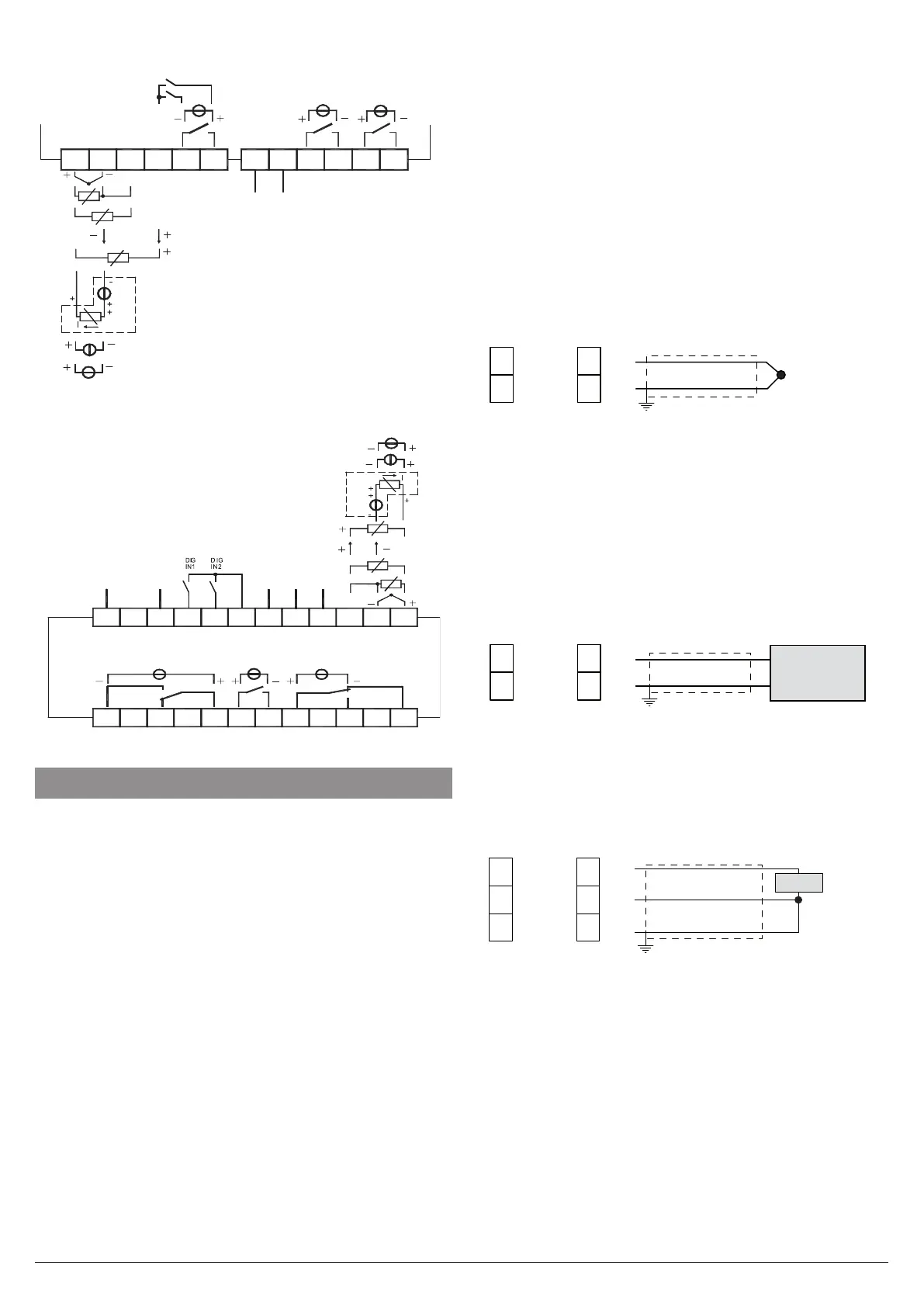
3.2 Inputs wiring
3.2.1 Ingresso da termocoppia
1
2
-
+
12
11
-
+
External resistance: 100 Ω max., maximum error 0.5% of span.
Cold junction: automatic compensation from 0 to 50°C.
Cold junction accuracy: 0.1°C/°C after a warm-up of
20 minutes.
Input impedance: > 1 MΩ.
Calibration: according to EN 60584-1.
Note: For TC wiring use proper compensating cable prefer-
able shielded.
3.2.2 Infrared Sensors Input
Exergen
1
2
-
+
12
11
-
+
External resistance: Do not care condition.
Cold junction: Automatic compensation from 0 to 50°C.
Cold junction accuracy: 0.1°C/°C.
Input impedance: > 1 MΩ.
3.2.3 RTD (PT100) Input
RTD
2
1
11
12
3 10
Input circuit: Current injection (135 µA).
Line resistance: Automatic compensation up to 20Ω/wire
with maximum error ±0.1% of the input span.
Calibration: According to EN 60751/A2.
Note: The resistance of the 3 wires must be the same.
 Loading...