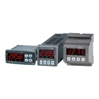
Ascon Tecnologic - K__V - Indicators - ENGINEERING MANUAL - PAG. 3
3.2.4 Thermistors Input
2
1
11
12
3 10
PTC/NTC
Line resistance: Not compensated.
Pt 1000 Input circuit: Current injection (25 µA).
3.2.5 V and mV Input
V, mV
+
-
1
2
-
+
12
11
-
+
Input impedance: > 1 MΩ
Accuracy: ±0.5 % of Span ±1 digit @ 25 °C.
3.2.6 Current Input (mA)
0/4... 20 mA input wiring for passive transmitter
using auxiliary pws
Trasmetitore
4... 20 mA
2 fili
-
+
1
2
-
12
-
3
4
+
11
10
+
0/4... 20 mA input wiring for passive transmitter
using an external pws
+
-
1
2
-
+
12
11
-
+
Trasmettitore
4... 20 mA
passivo
Alimentatore
esterno
-+
0/4... 20 mA input wiring for active transmitter
-
+
1
2
-
+
12
11
-
+
Trasmettitore
4... 20 mA
attivo
Input impedance: < 51Ω.
Accuracy: 0.5% of Span ±1 dgt @ 25 °C.
Protection: NOT protected from short circuit.
Internal auxiliary PWS: 10 VDC (±10%), 20 mA max..
3.3 Output
Safety notes:
– To avoid electrical shock, connect power line at last.
– For supply connections use No. 16 AWG or larger wires rated
for at last 75°C;
– Use copper conductors only.
– SSR outputs are not isolated. A double or reinforced isola-
tion must be assured by the external solid state relays.
3.3.1 Output 1 (OP1)
Relay Output
CNCNO
22
23 24
CNCNO
3
4 5
CNO
11
12
NO NC
13
14 15
C
1716
Out 1 contact rating: • 8 A /250 V cosj =1;
• 3 A /250 V cosj =0.4.
Operation:
1 x 10
5
.
Uscita SSR
+-
22
23 24 3
4 5 11
12 13
14 15 1716
+- +-
Logic level 0: Vout < 0.5 VDC;
Logic level 1: 12 V ±20% @ 1 mA;
10 V ±20% @ 20 mA.
3.3.2 Output 2 (OP2)
Relay Output
CNCNO
19
20 21
CNCNO
6
7 8
CNO
9
10
NO NC
20
21 22
C
2423
Out 2 contact rating: • 8 A /250 V cosj =1;
• 3 A /250 V cosj =0.4.
Operation: 1 x 10
5
.
SSR Output
+-+- +- -+
19
20 21 6
7 8 9
10 20
21 22 2423
Logic level 0: Vout < 0.5 VDC;
Logic level 1: 12 V ±20% @ 1 mA;
10 V ±20% @ 20 mA.

 Loading...