Ascon Tecnologic - K__V - Indicators - ENGINEERING MANUAL - PAG. 4
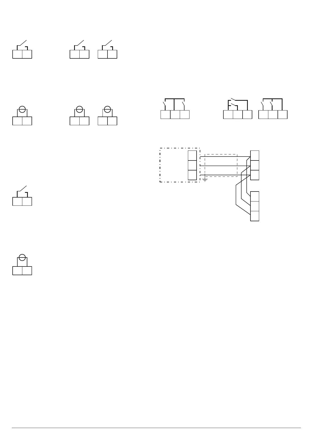
3.3.3 Output 3 (OP3)
Relay Output
CNO
9
10
CNO
17 18
CNO
18 19
Out 3 contact rating: • 8 A /250 V cosj =1;
• 3 A /250 V cosj =0.4.
Operation: 1 x 10⁵.
SSR Output
+-
9
10
+-
17 18
+-
18 19
Logic level 0: Vout < 0.5 VDC;
Logic level 1: 12 V ± 20% @ 1 mA;
10 V ± 20% @ 20 mA.
3.3.4 Output 4 (OP4)
Relay Output
CNO
15 16
Out 1 contact rating: • 8 A /250 V cosj =1;
• 3 A /250 V cosj =0.4.
Operation:
1 x 10
5
.
SSR Output
+-
15 16
Logic level 0: Vout < 0.5 VDC;
Logic level 1: 12 V ± 20% @ 1 mA;
10 V ± 20% @ 20 mA.
3.4 Logic Inputs
Safety notes:
– Do not run logic input wiring together with power cables.
– Use an external dry contact capable to switch 0.5 mA,
5 VDC.
– The instrument needs 150 ms to recognize a contact sta-
tus variation.
– The logic inputs are NOT isolated by the measuring input.
A double or reinforced isolation between logic inputs and
power line must be assured by the external element.
5
6 7 6
7 8
6 7 8
DI1 DI2 DI1DI2DI1 DI2
3.5 Serial Interface
10
8
9
A/A’
B/B’
GND
Master
A/A’
B/B’
C/C’
7
8
9
A/A’
B/B’
GND
K85
Interface type: - Isolated (50 V) RS-485;
- TTL not isolated;
Voltage levels: According to EIA standard;
Protocol type: MODBUS RTU;
Byte format: 8 bit without parity;
Stop bit: One;
Baud rate: Programmable: 1200... 38400 baud;
Address:
Programmable: 1... 255.
Notes: 1. RS-485 interface allows to connect up to 30 devi-
ces with one remote master unit.
2. The cable length must not exceed 1.5 km at
9600 baud.
 Loading...