© 2023 United States Stove Company
9
vi
X 6
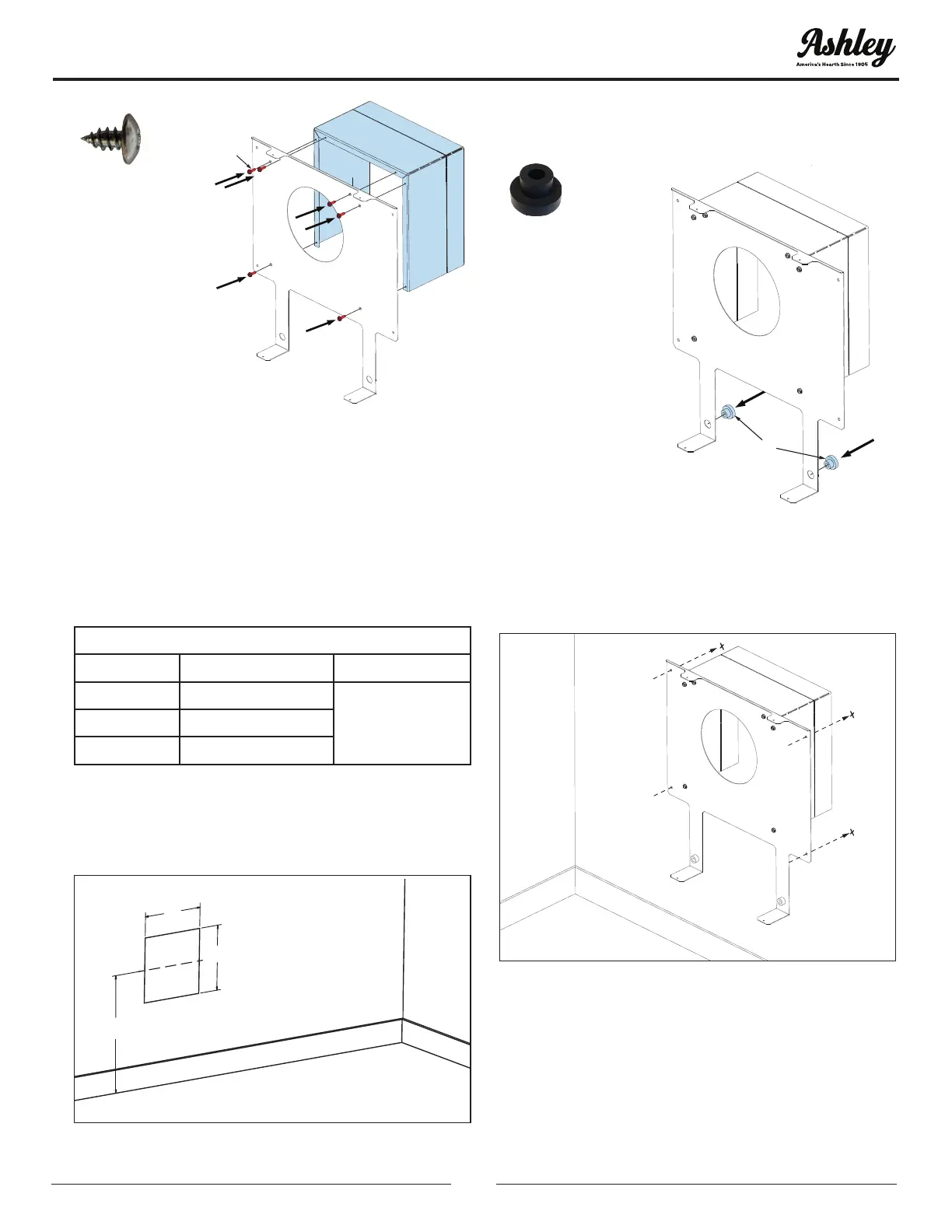
Figure 10
2. Draw the position of the hole for the air-vent
intake pipe, taking into account the minimum
clearances mentioned in Figure 6. See the
dimensions of the square hole “D” and height
to the center “C” in Table 1 and Figure 11 for the
different models. Height “C” is the minimum
recommended.
TABLE 1
MODEL C D
DVAG11-DF 20-7/32” (514 mm)
11-1/4” X 11-1/4”
(286 x 286 mm)
square hole
DVAG17-DF 20” (508 mm)
DVAG25-DF 25-7/16” (647 mm)
3. Cut the square hole through the wall according
to the measurements and positions indicated
in the gure below.
C
D
D
Figure 11
4. Insert the two provided rubber grommets (v)
into the lower bracket.
v
X 2
Figure 12
5. Place the hanging bracket over the square hole.
Check to see if the bracket is level. After leveling
the hanging bracket, mark the four holes.
Figure 13
6. Remove the hanging bracket and drill
the four holes using a masonry drill bit.
NOTE: The masonry drill bits size must match
the size of the masonry screw that will be used
(masonry screws and drill bit not included).
INSTALLATION


 To Next Page
 Loading...