2022/03/16 04:45 15/18 MS2000, MFC2000 and RM2000 OPERATION
Applied Scientific Instrumentation - https://asiimaging.com/docs/
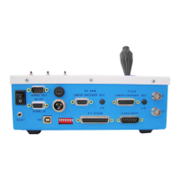
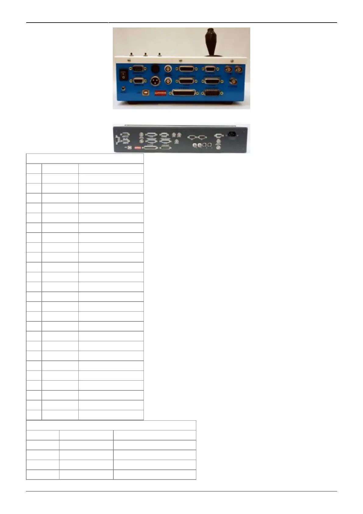
X-Y Stage DB-25F Connector
PIN SIGNAL INFORMATION
1 X Mot - X Motor -
2 X GND X Encoder Ground
3 X Enc Ch A X Encoder Channel A
4 Y Mot - Y Motor -
5 Y GND Y Encoder Ground
6 Y Enc Ch A Y Encoder Channel A
7 N.C. Not Connected
8 N.C. Not Connected
9 N.C. Not Connected
10 X Lim U X Upper Limit
11 +5V +5V (X-limits)
12 Y Lim U Y Upper Limit
13 +5V +5V (Y-limits)
14 X Mot + X Motor +
15 +5V +5V (X-encoder)
16 X Enc Ch B X Encoder Channel B
17 Y Mot + Y Motor +
18 +5V +5V (Y-encoder)
19 Y Enc Ch B Y Encoder Channel B
20 N.C. Not Connected
21 N.C. Not Connected
22 X Lim L X Lower Limit
23 GND Ground (X-limits)
24 Y Lim L Y Lower Limit
25 GND Ground (Y-limits)
Z-Axis Drive & Optional F-Axis DB-15M Connector
PIN SIGNAL INFORMATION
1 F Enc Ch B F Encoder Channel B
2 Z Lim L Z Lower Limit
3 F Lim L F Lower Limit
4 F Mot - F Motor -